Cables and Biss-C Encoder DIY for AKM54K motor

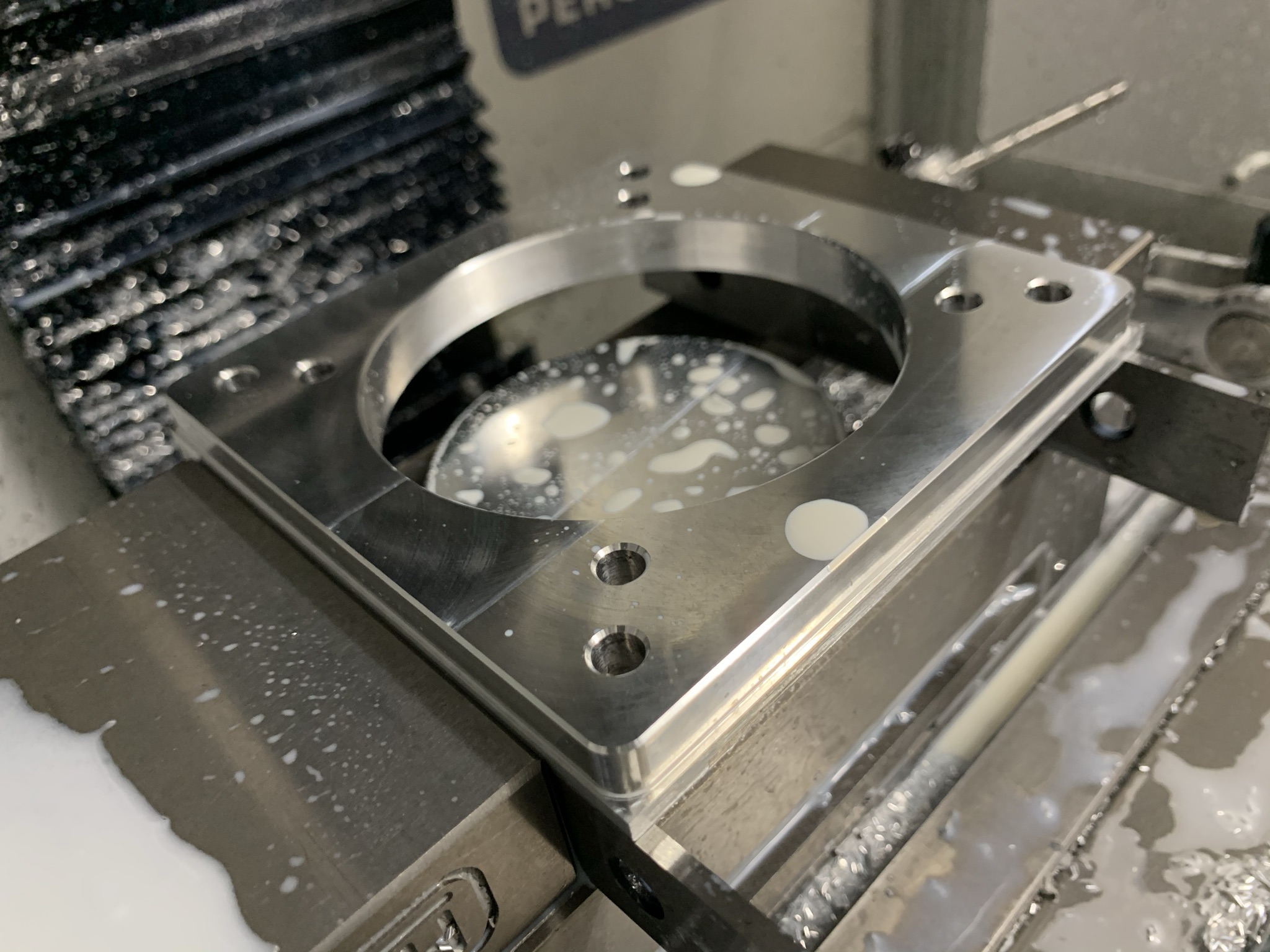
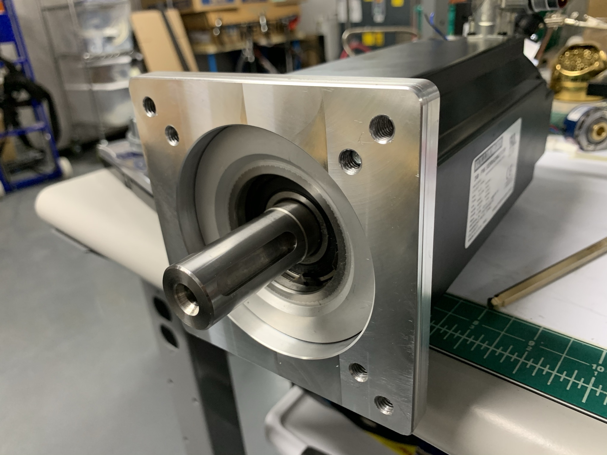
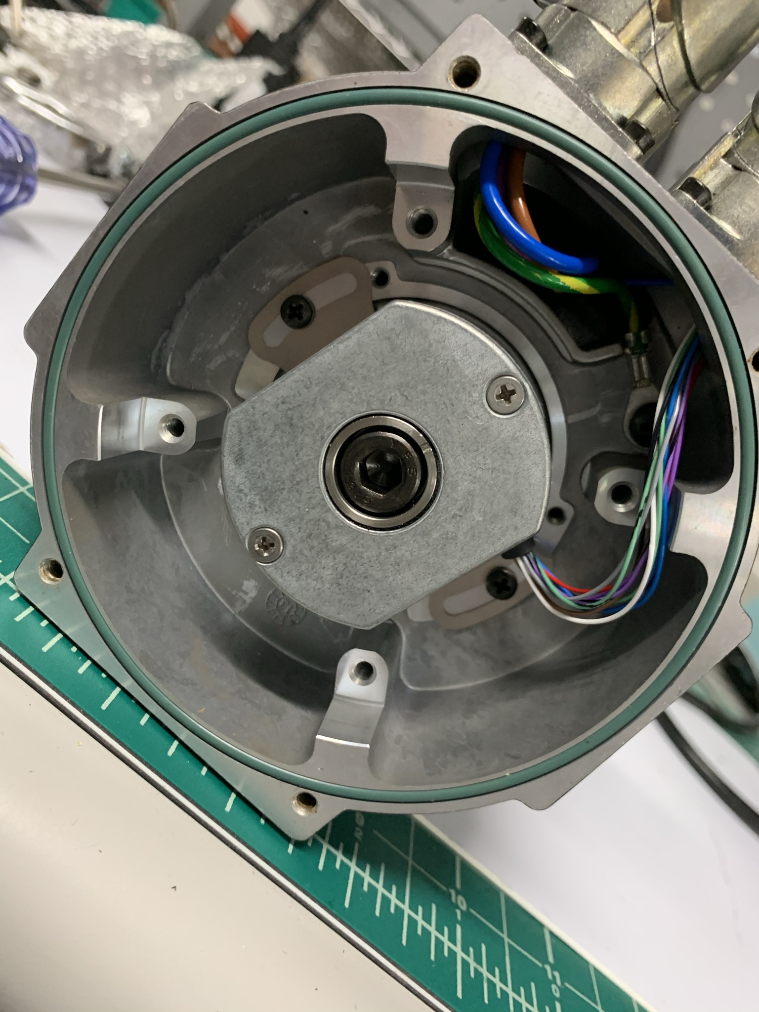
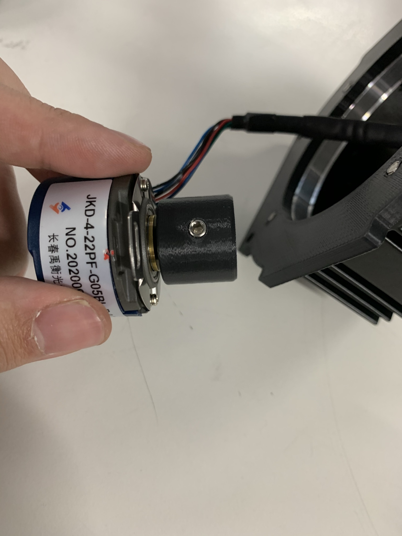
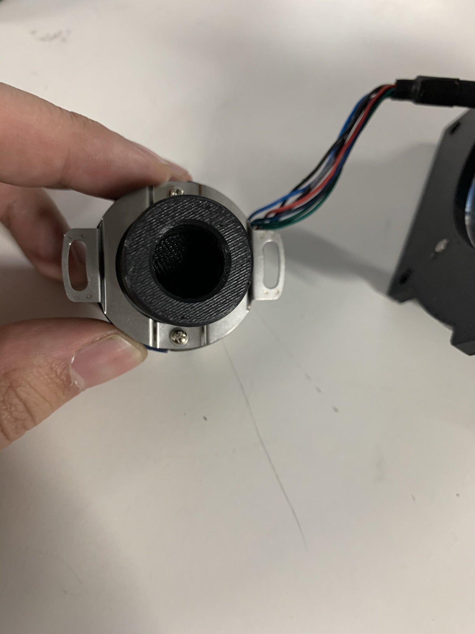
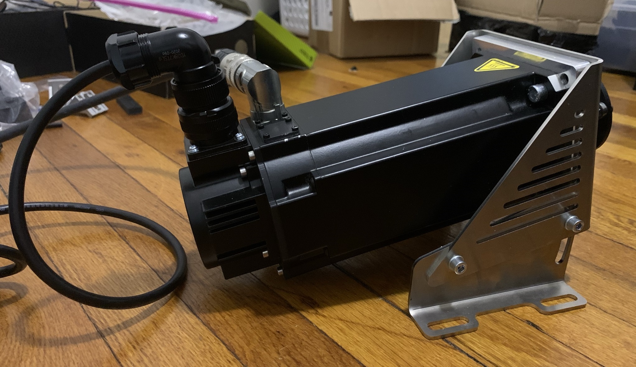
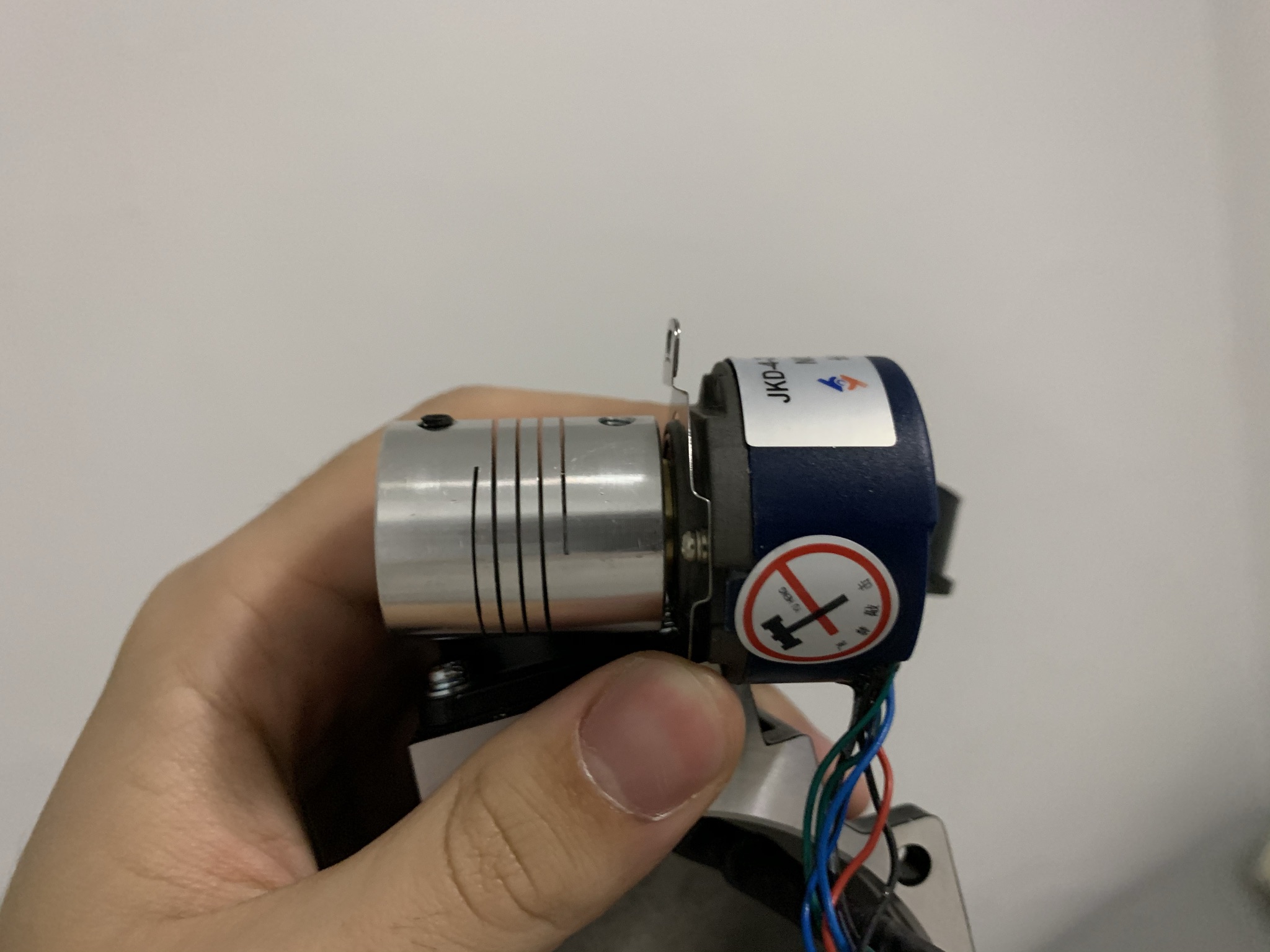
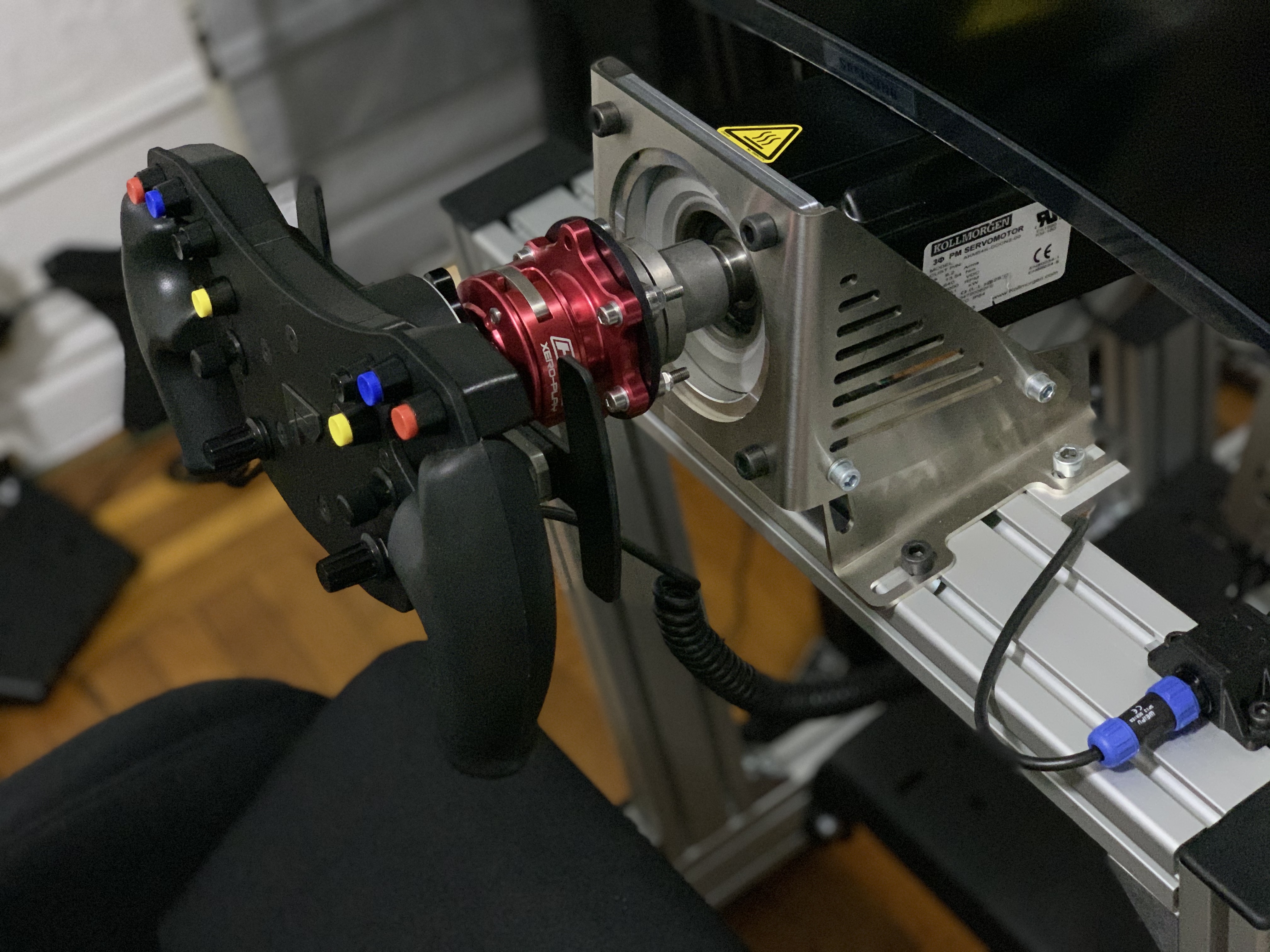
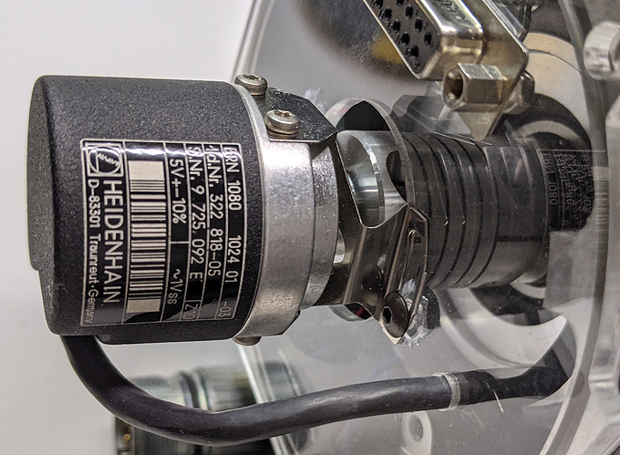
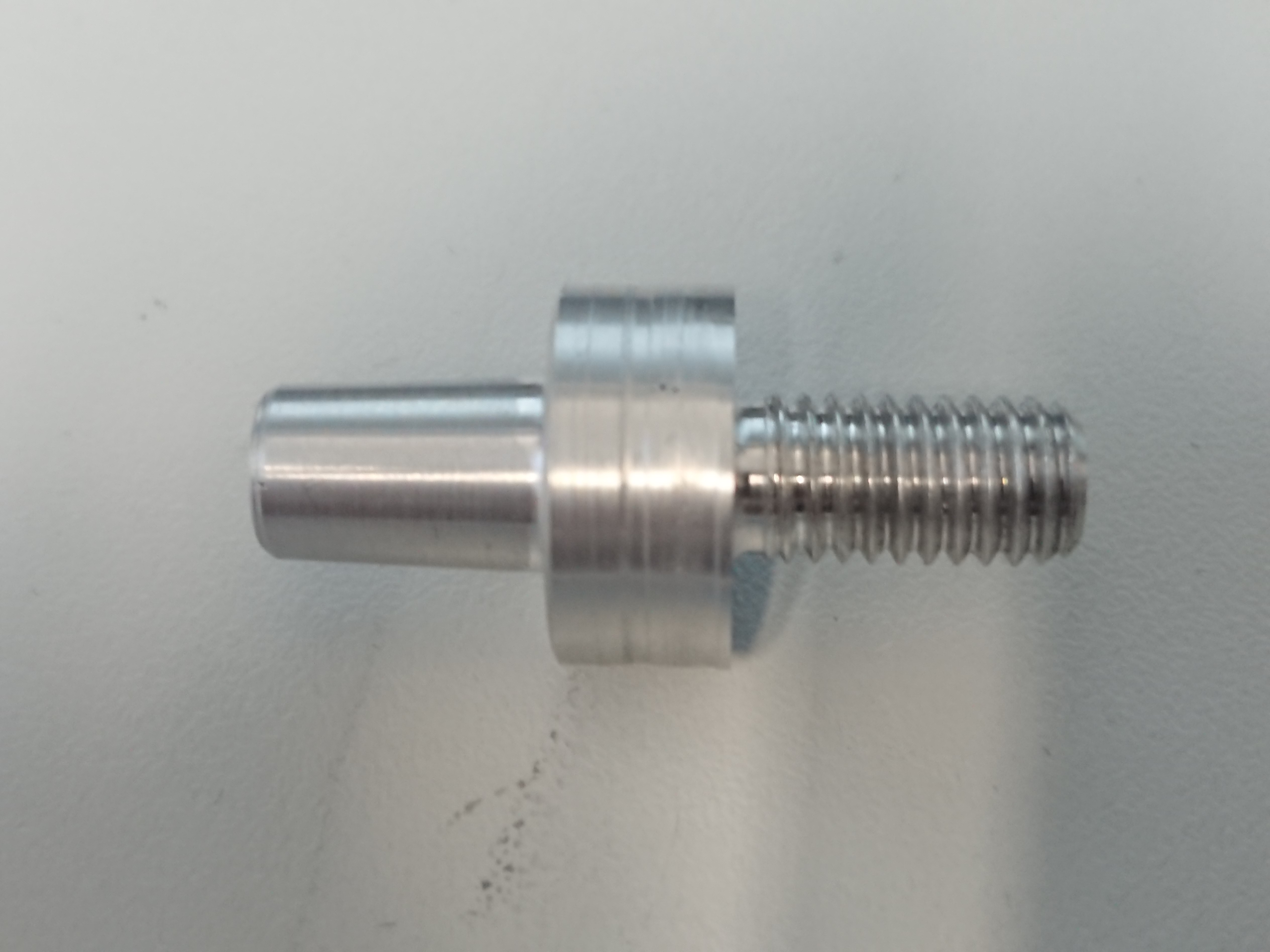
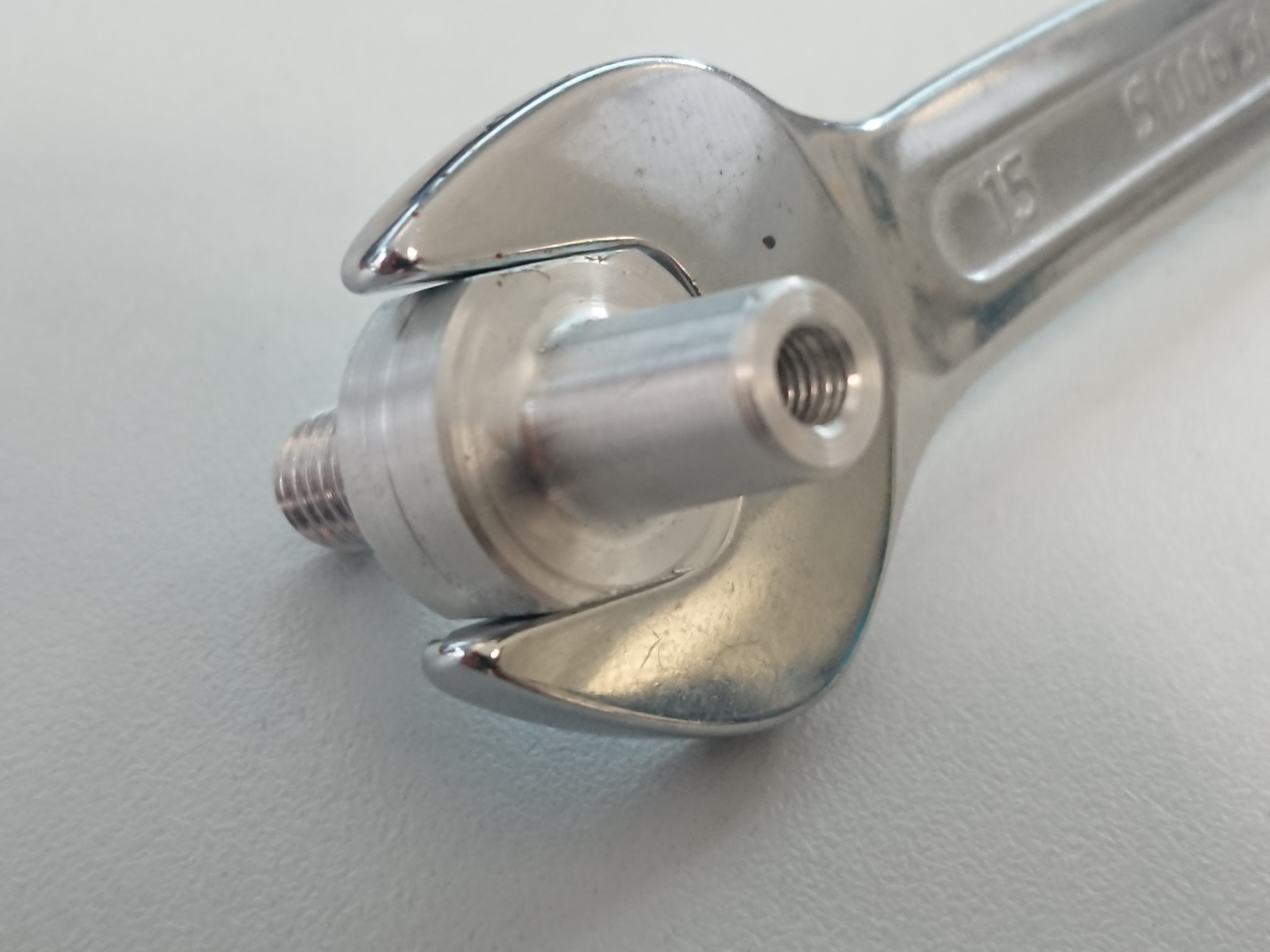
Scored a pretty affordable AKM54K Kollmorgen servo, will be building a simucube 1 system with it. The servo has a basic 8k encoder, I will be adapting a mige biss-c encoder to the servo, I’ve already been discussing the project with a few gurus, and I have access to some aluminum machining services through a friend of mine.

Servo is in the mail and I need to order the mige biss-C, a few questions:

  1. I have the ability to make my own cables to my own specified length, just need to source the connectors. Is there a guide on where to get the exact power connectors for an AKM54K? It looks like an M23 connector, 8 pin, but not sure if there are different lengths etc

  2. What size cable should I use for power and encoder? Should I size to 25A for Ioni Pro HC? Would 16 AWG suffice or should I up to 12, same question for the encoder cable.

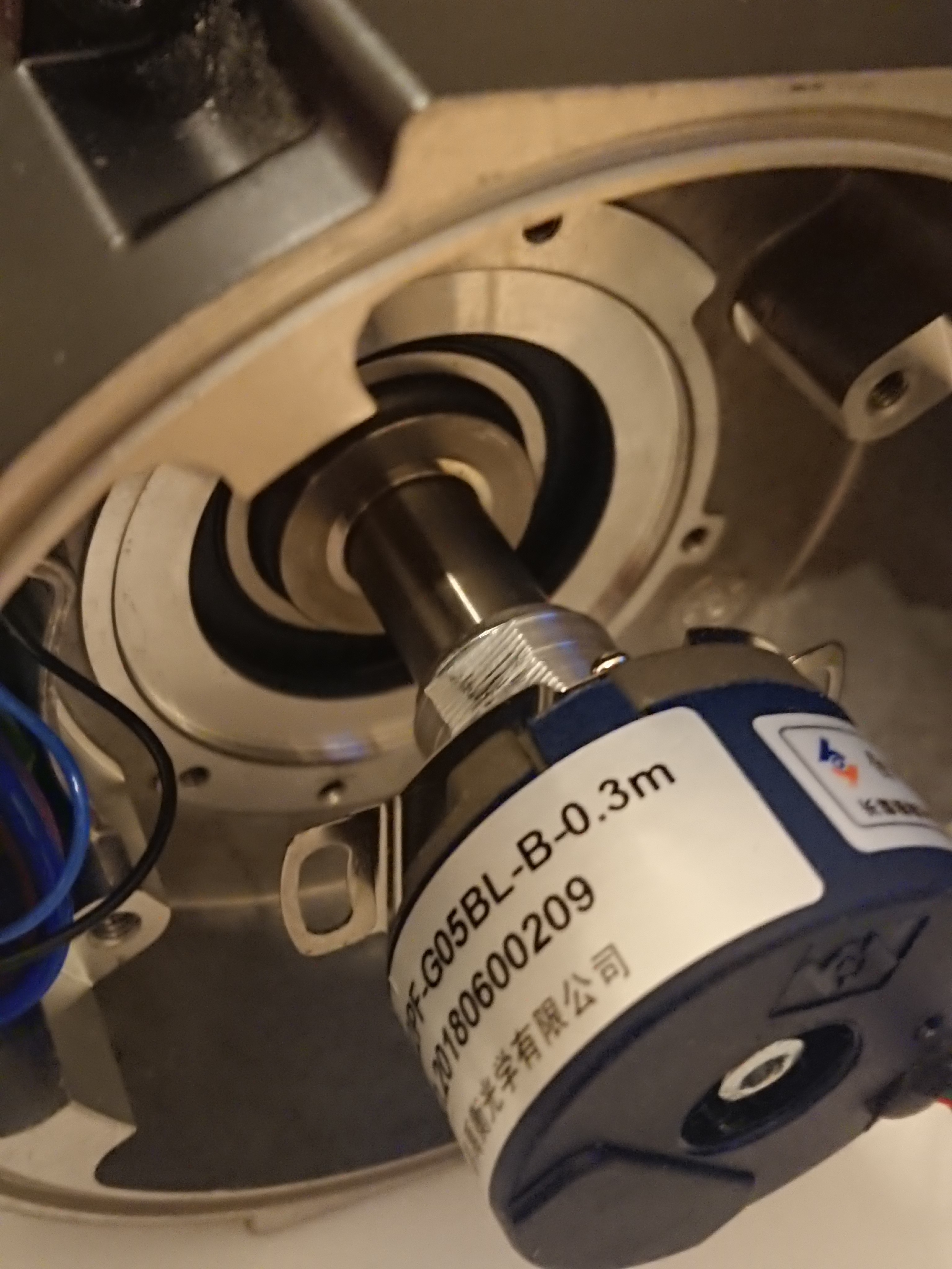
  3. Does anyone know the mige connector that is used for the encoder? Would like to try to source that as well if its cost effective, if not I’ll just include it in my order from Lisa (unless someone has a mige biss-c they want to let go of/sell)

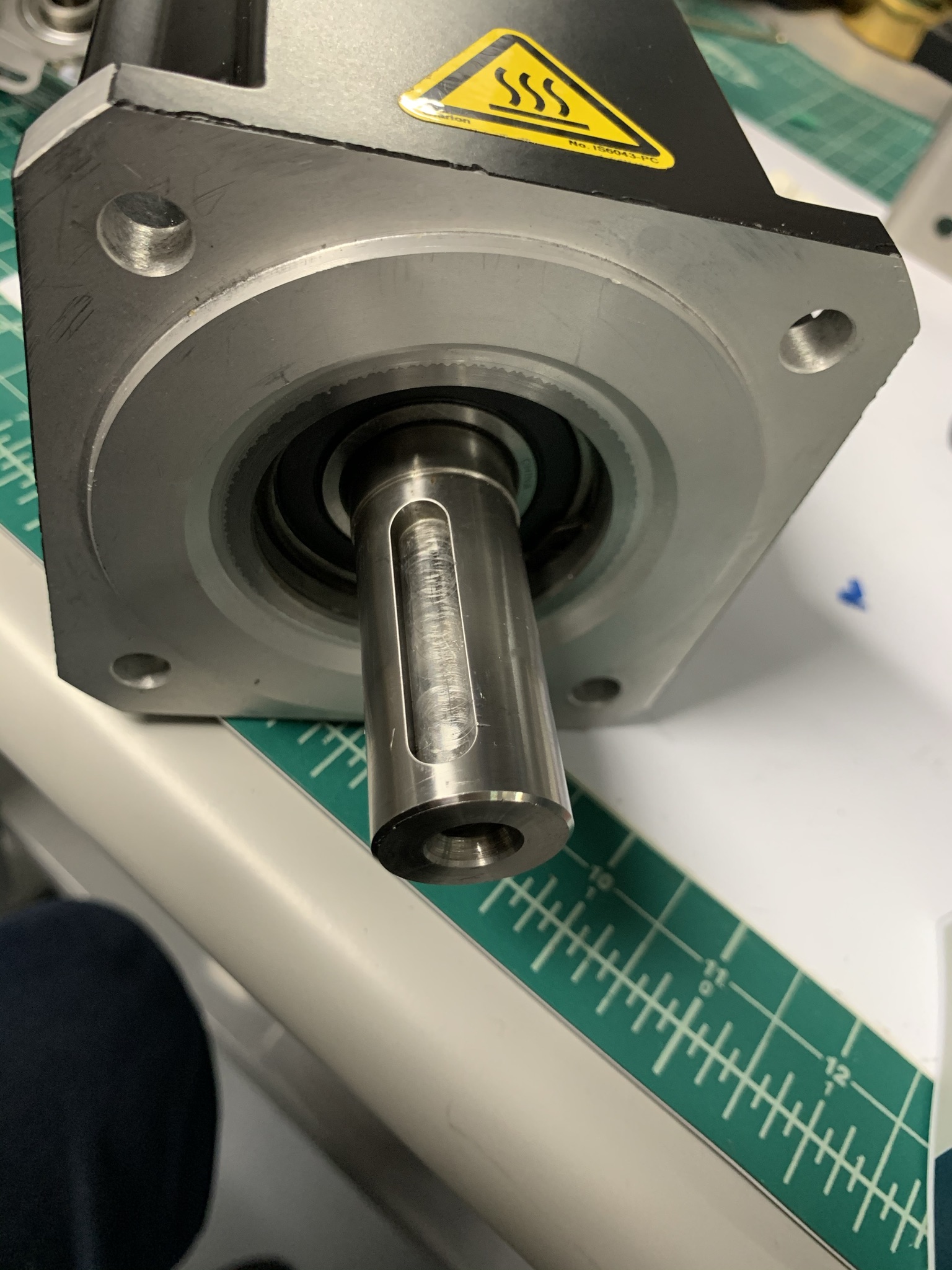
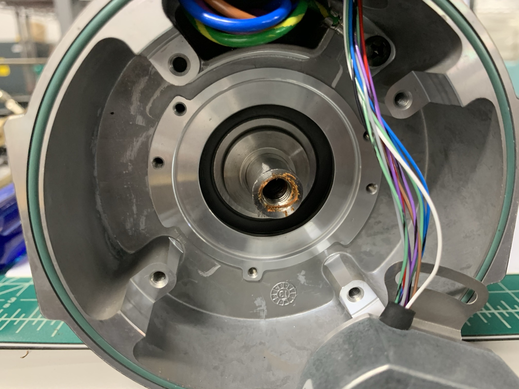
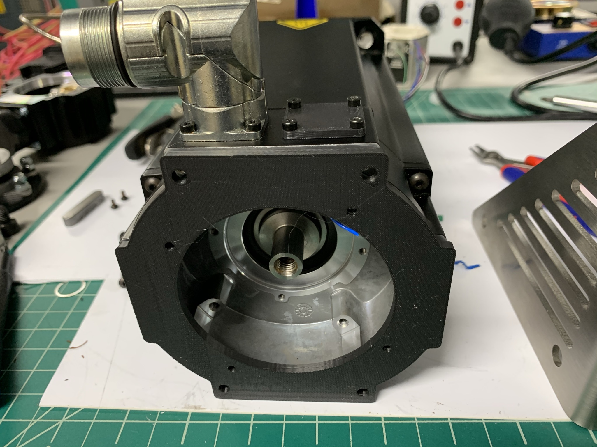
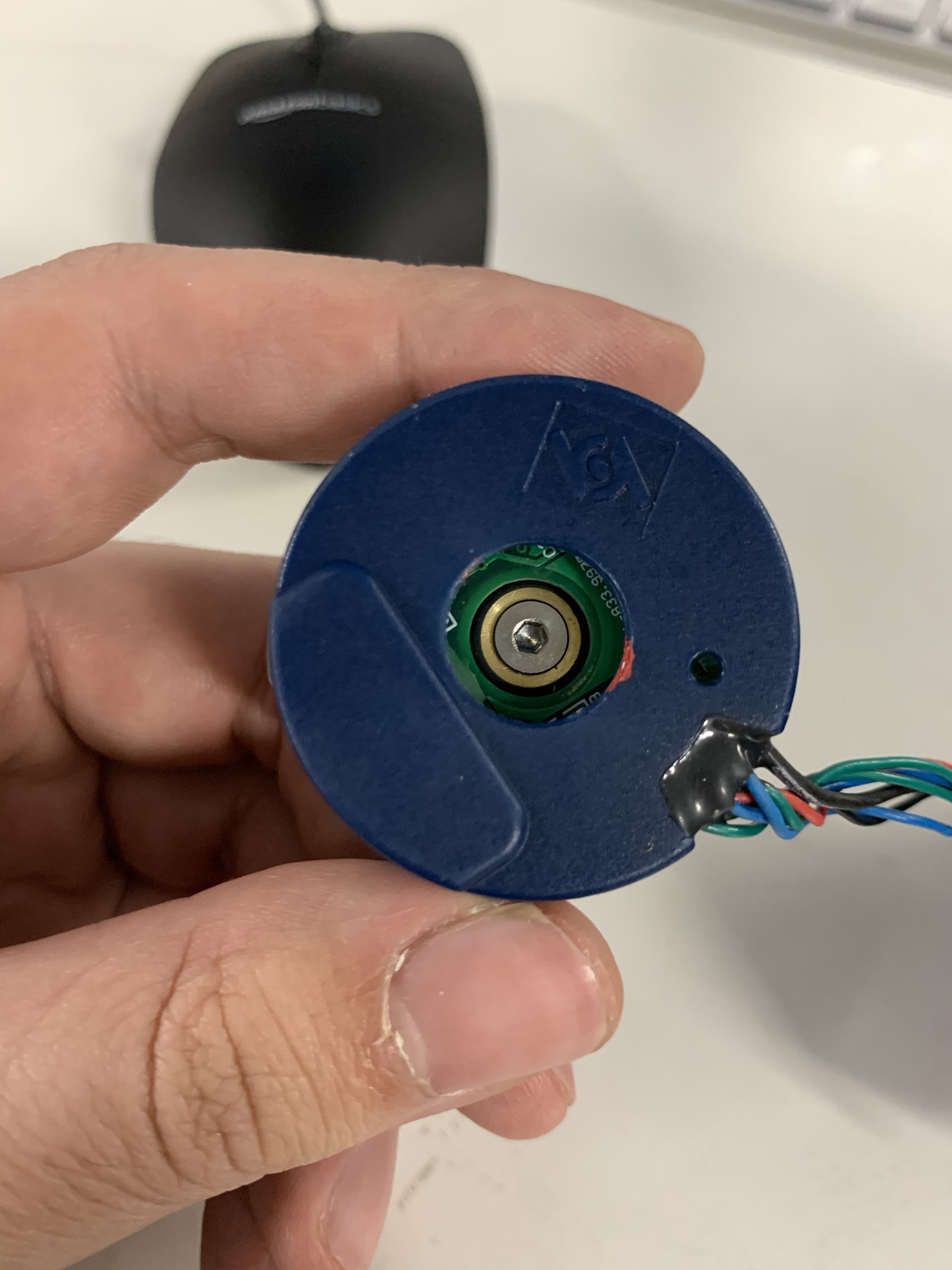
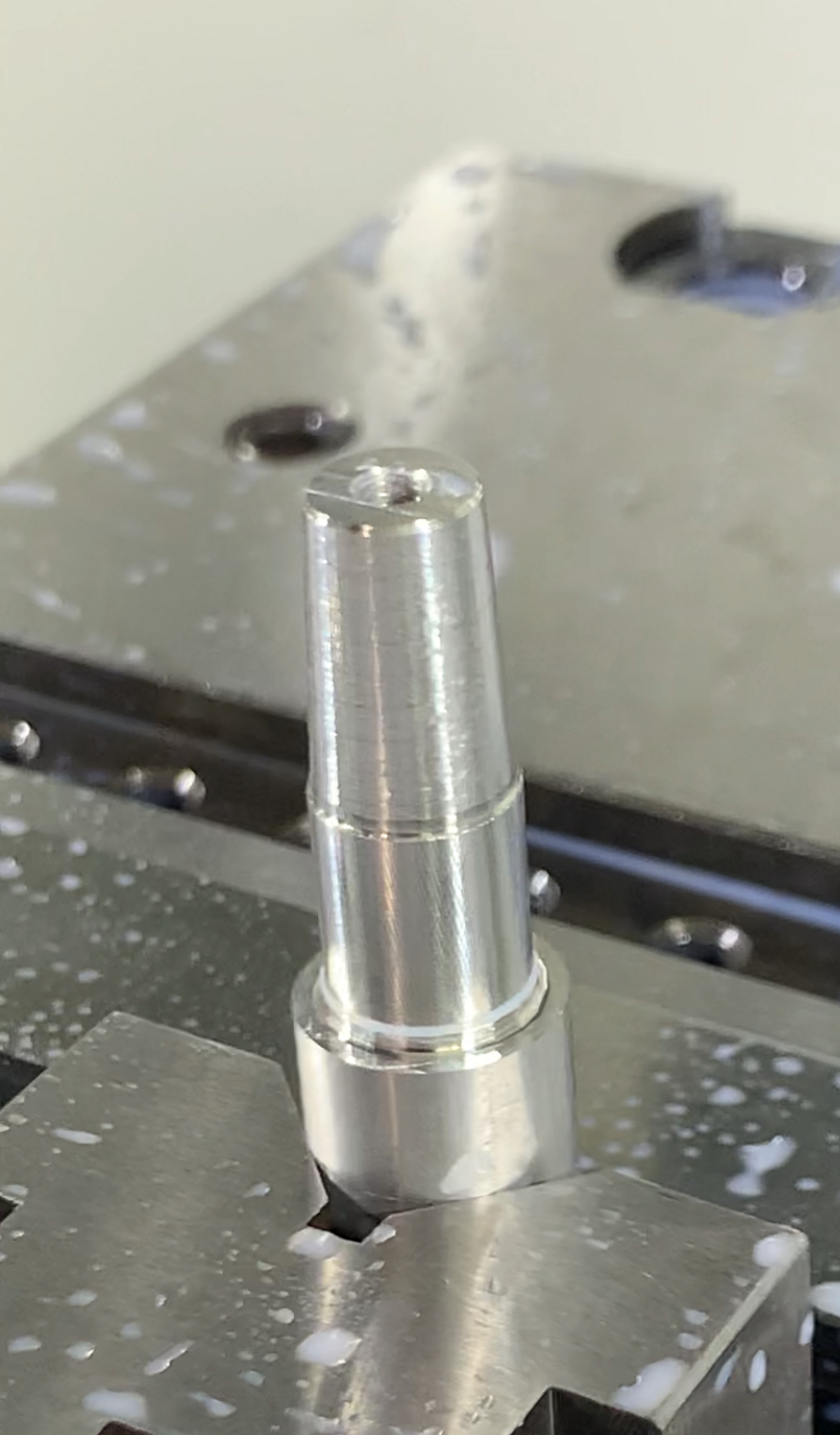
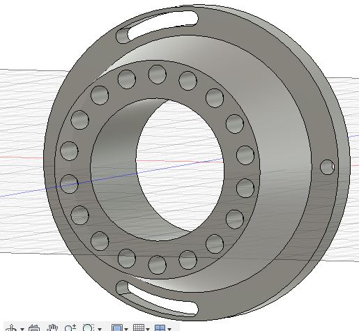
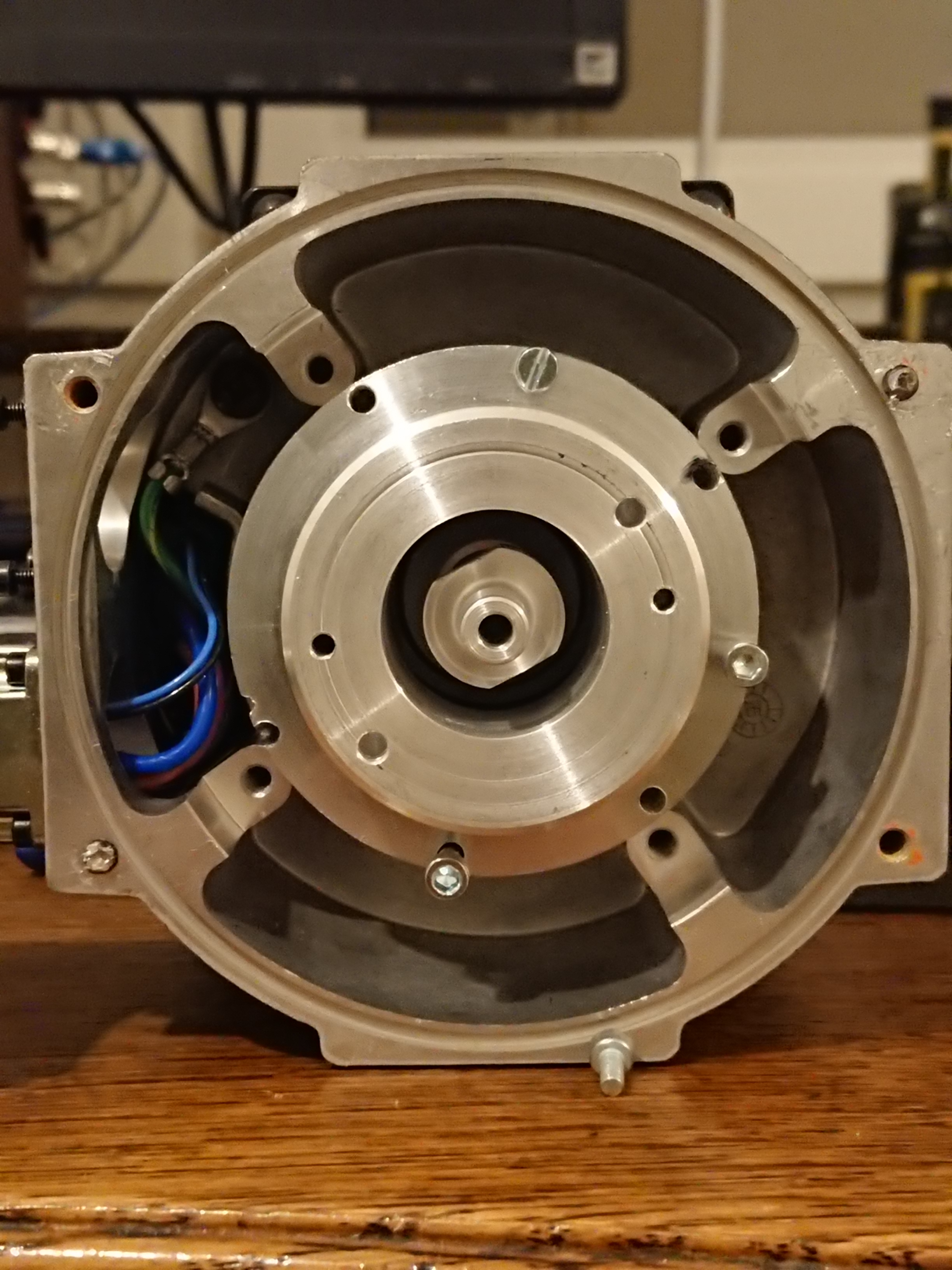
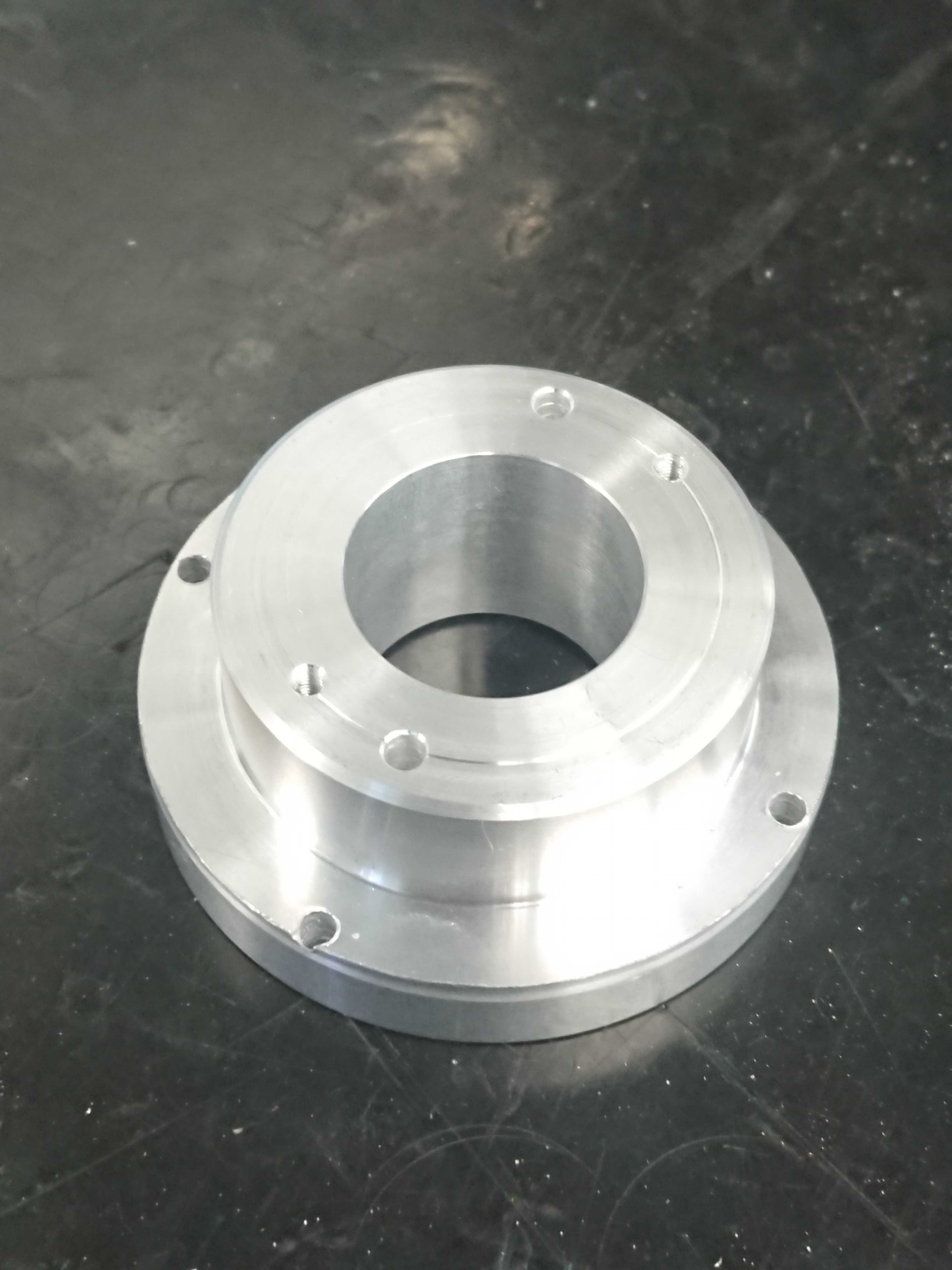
  4. What are the dimensions and taper for the biss-c encoder and rear end of the shaft on the AKM54K? Can’t find that spec anywhere. Need this to adapt the AKM54K to the mige biss-c

For reference, the model code for the motor is AKM54K-CCCN2-00

1 Like

I think I may have been watching that same servo on eBay - if you got it, nice!
This was basically my plan as well - I have an AKM52k with a 2048ppr encoder.

To adapt the AKM shaft to the Biss-C, I think might be a bit of a guessing game until you get the servo opened up.
However, this thread on the iRacing forums shows Sam Maxwell converting an AKM52G to a Heidenhain - the shaft on the AKM5x I believe to be standard across the variants, which Sam measures at 12.7mm. In his case, the Heidenhain accepts a 6mm shaft, so he is able to use a 12.7mm x 6mm CNC coupler.

https://members.iracing.com/jforum/posts/list/3575176.page

The Mige Biss-C however, accepts a tapered shaft, which starts at 9mm OD, and ends at 8mm OD, with a nose on the end which is tapped I think to M5 - I haven’t translated the drawing - but I’m attaching it. So you could use a couple much like Sam, just have to make an adapter shaft.

I drew up an overly long STL file, with the intent to 3D print the shaft adapter, and trim to length to fit the Biss-C reasonably. In Sam’s example above (I’ve attached a photo) with the Heidenhain, you’ll see it no longer fits in the AKM’s cover, so he cut a custom backplate from plexi/lexan. You can likely do the same as he shows.

Here’s the drawing for the Biss-C encoder with the dimensions - I’m a few years out of machinist school so I may be mis-reading, but I think I’m close.

If you want the STL file I made, let me know, I haven’t printed any (don’t have a Biss to convert with…yet). Like I said, it’s overlong to cut to size, but it is tapered, and has a solid nose on the end for drilling/tapping to attach to Biss. Though - it may be that’s actually to release the encoder from the shaft…never had one apart to know, and the drawings don’t make it clear…Also, I think my STL is 9mm diameter shaft - but I don’t readily see a 9mm x 12.7mm coupler, but that could be easily upped to a more common diameter (10mm maybe) so you’re not searching high and low for a rare coupler.

Biss-C Drawing/Datasheet

Hey,

I did grab that one, I just got it delivered 10 minutes ago. It’s smaller than I thought, it has a 95mm hole spacing instead of the mige 110mm. Can’t wait to start messing around. Did you hook up the 52K with the 2048 encoder? How does it feel with that resolution?

Thank you for the drawing. I ordered a Biss-C from Lisa, so thats probably a week out. I wouldnt mind checking out the STL file, if you cant upload it here I can send my email. I’m going to try to open it up and remove the encoder this weekend and I’ll post what it looks like.

Well - I’m exited to watch your progress!

The 2048 isn’t bad at all - I don’t have much to compare it to, however, as I went from a Logitech G27 to my DIY Simucube 1 AKM52 build. I imagine the fidelity gets better with a higher resolution encoder, and I’ll someday update it - just haven’t e-mailed Lisa to order one yet. But with proper profiles set for iRacing, and custom FFB for Project Cars2 and Automobilista 2 - the Simucube is really a treat; even with the lower rez encoder, the curbing, road texture, steering feedback/etc., are really very impressive and similar to my real world vintage race cars.

Here’s a link to the STL: https://www.dropbox.com/s/4z6c98f3ode0mpt/mige-kollmorgen-shaft-taper_m5.stl?dl=0

It’s not much, I used Tinkercad, YMMV - feel free to use it, or trash it :slight_smile:

This coupler on eBay may just work; or, make that STL file a hair larger diameter to 10mm and get a standard 12.7mmx10mm coupler.

I’ve heard horror stories on getting the AKM’s apart, Sam may mention in his thread a disassembly method. I understand heat application, and good tight fitting allen keys are necessary.

I should just pull the trigger and buy the encoder and cables, and put them on the shelf until I can take my SC1 out of action for a bit. :thinking:

And obviously, if you have machining capability, you can just have your own coupler machined. easy peasy!

Thanks for the STL. You can wait till I do the experiment if you want haha, I might build an encoder cable and just use it with the 2k encoder until my biss-c comes in. But my simucube/iono hc havent shipped yet for some reason.

International bank money transfers take a few days to show up on our account, order will be cleared when it checks out.

1 Like

Posting an update since I received the parts and had my friend help me make a couple of things. Big shoutout to Brion Sohn and Joe Sullivan for all the help answering my questions.

First I had to make an adapter mounting plate since my hole pattern is non-standard, so we CNCed an aluminum plate with threading holes to adapt to an augury mige mount.

Then we took apart the encoder. Has to use heat on the bolts on the backplate since they had threadlocker. Then the encoder came off pretty easy, just had to loosen the m8 bolt and take off the mounting screws and it came right off.

Then we 3d printed a backplate to adapt the biss-c and a cover for the old encoder connector

Then we 3d printed the adapter shaft/coupler in one piece to test fitment. The encoder shaft on the AKM is half inch, the biss-c is 9mm with a 1/10 taper, meaning for every 10mm of length the diameter goes down by 1mm. the tapered portion is 13.5mm long, so it goes from 9mm diameter to 7.65mm diameter. The coupler portion had holes for 2 set screws. I will upload the cad file when I get it its on my friends computer.

We tapped the end of the tapered portion with an m3 screw

And this is the final motor assembly from the back

Now i’m just messing with Granity/Simucube settings to get this thing dialed in, then next is machining the shaft parts from aluminum.

5 Likes

Nice job young man!
I am very proud of you for not giving up!!:slight_smile:

1 Like

Awesome!! Fitment of the Biss isn’t too terrible then - if you wouldn’t mind sharing the STL files for the adapter and housing I would greatly appreciate it. I’ll tuck them away until I get up the gumption to crack open my AKM.

Curious what encoder came out of it, guessing probably a 2048ppr Accu-Coder?

Nice work!!

Yes it was a 2048 accu-coder. I’ll get the STL files from my friend he drew it up on his work PC I’ll remind him to send them to me.

Do note than my motor is a “CC” mounting code designation, and as noted on page 39 in this pdf

(https://www.raveo.cz/sites/default/files/dokumenty/[katalog]_Kollmorgen_AKM_Selection_Guide_2014_EN.pdf)

it is a bit smaller than other servos. So the backplate design for example that was linked in the thread you gave me didnt fit and we had to redo it.

The 3d printed shaft should work though. I haven’t put it through it’s paces but after tightening it down with the set screws it seems fine. We also printed a spacer to mount the biss-c onto the mounting holes on the back of the AKM, it doesnt bolt directly the the backplate. I actually bought the 9.5mm to 12.7mm coupler from ebay that you linked and we will be machining the tapered shaft from metal to use with that. I will post all the files here when I have them.

1 Like

Machined the shaft out of aluminum this past weekend, perfect fit. We made it a tiny bit shorter than the specified 13.5mm on the drawing, made the fit a little better.

Fit well on the 9.5mm to 12.7mm coupler

And just a glamour shot of the motor mounted up on the rig, xero play QR from HRS (ignore the missing bolt I was just testing fitment when I took the pic)

I had to print an 11mm spacer to accommodate the coupler since it is longer than the first part we made. I will post all the final CAD files sometime this week

5 Likes

Nice work! I would like to do this to my AKM servo motor soon!

I am glad to see such a rebuild here. Such a conversion also appeals to me.

Could you please share the STL for the adatper (housing of the Encoder)? I would highly appreciate that.

How did you couple the anti-rotation clamp to the housing?
The diameter is different. Also the distance needs to be gapped. 3D print as well?

This my current status:

I didn’t want to use a coupling, so I made one Pin to extend the Shaft and mount the encoder. But I made it to short, to secure it as shown above:

To ensure the function, only the encoder has to be screwed to the housing.
Then I will take care of a suitable cover and also mount a D-Sub connector.

1 Like

It is fantastic to see someone do very nice engineering. :+1:

1 Like

Thank you Mika for the recognition.
I am always pleased that you (personally and the whole team) have created this great system and, above all, that you continue to develop it.

I can allready feel the much lower inertia of my AKM53G compared to the Mige, what is great!
But I also feel the cogging torque.
Since this is a uniformly repeating ripple, I wonder if you can’t compensate for it in SW.
You would “only” need 3 parameters to compensate it with an added torque vector:
Pole pair number
Amplitude
Phase

But that is a different topic and does not belong here.
EDIT:
of course, this has been integrated for ages… Good work GD-team.
Now I just have to fine tune here
https://granitedevices.com/wiki/Configuring_cogging_torque_compensation

Now I have to take care of the production of the adapter :slight_smile:
Encoder

1 Like

Since 3D printing would have taken too long (I don’t have a printer myself), it was milled from aluminium.
Unfortunately, the first holes were not very accurate. But then it worked out well.
The first tests will follow at the weekend. After that, a new cover will be put on the back. But that is not urgent.

2 Likes

This is all excellent stuff! I need to put a Biss encoder on my Christmas list…Really makes me want to upgrade my AKM, good to see everyone innovating.

Might also be good leverage to finally buy a 3D printer… :nerd_face:

1 Like

First impressions of the AKM53G servo compared to the small Mige. Both with SC1 and Biss-C.

Neutral

  • Other design
  • About the same amount of torque due to the limitation of my PSU.

PRO

  • less inertia. Thus more dynamics. Just less low-pass behavior of the FFB.
    Helps especially with rapid load changes such as countersteering in sudden oversteer events.

CON

  • ignificantly higher cogging torque. Noticed less at high loads (like fast curve). If little FFB level is present it is more pronounced, for example when driving slowly and steering around the zero steering angle on the straight.

  • More noise (high frequency beeping) due to the actuation (even in standby).

I hope that I can still artificially compensate for the cogging by tweeking the firmware. Then it would be really great!

1 Like