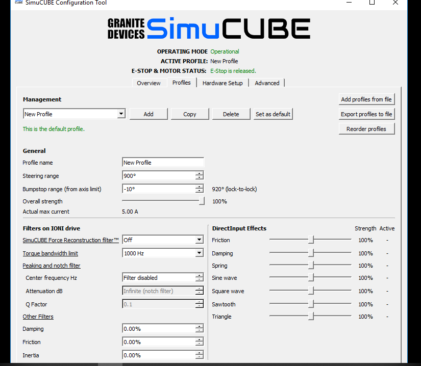
Hi everyone i bought my simucube setup last week and cant get the wheel to move in the overview
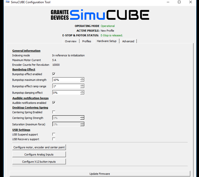
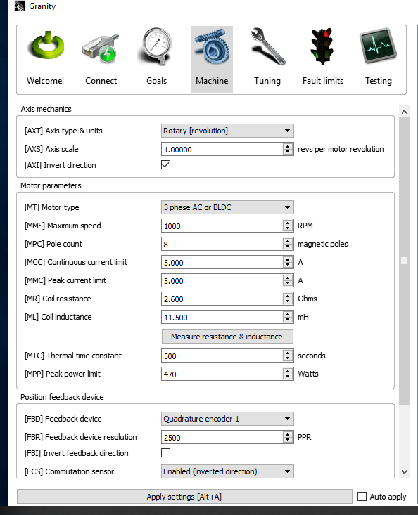
i have posted my settings above …im using a 2500ppr small mige… in hardware settings it has encoder counts as 10000 …
theres is not load on the motor when i turn it and the wheel in overview doesnt move i have a mate with a simucube setup who helped me set it up but still no luck any ideas ?
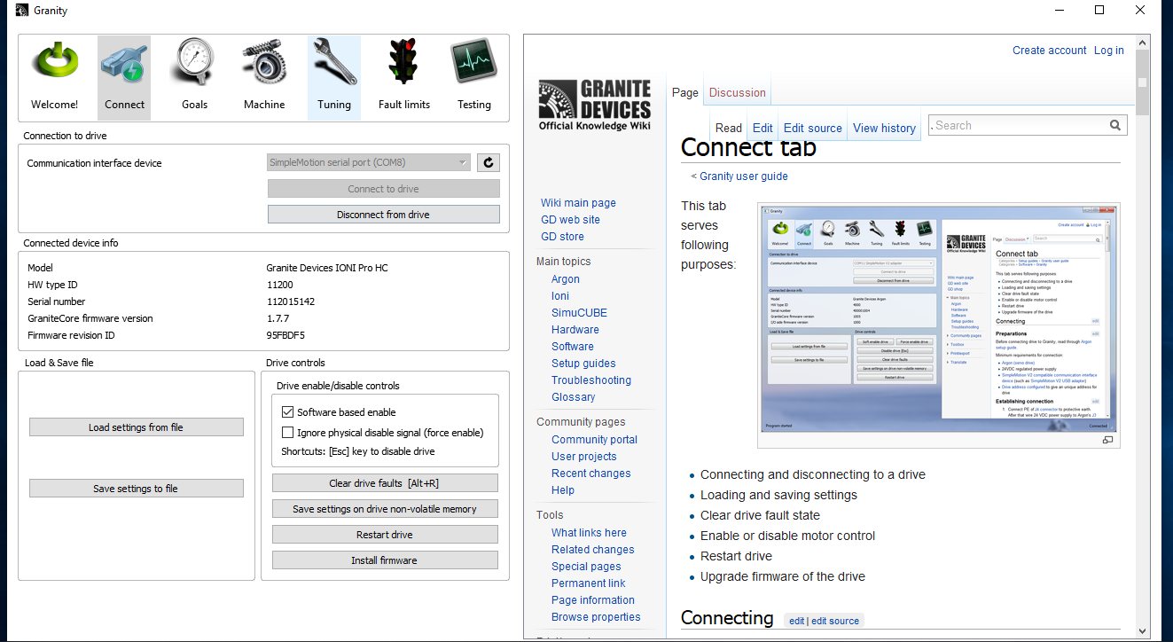
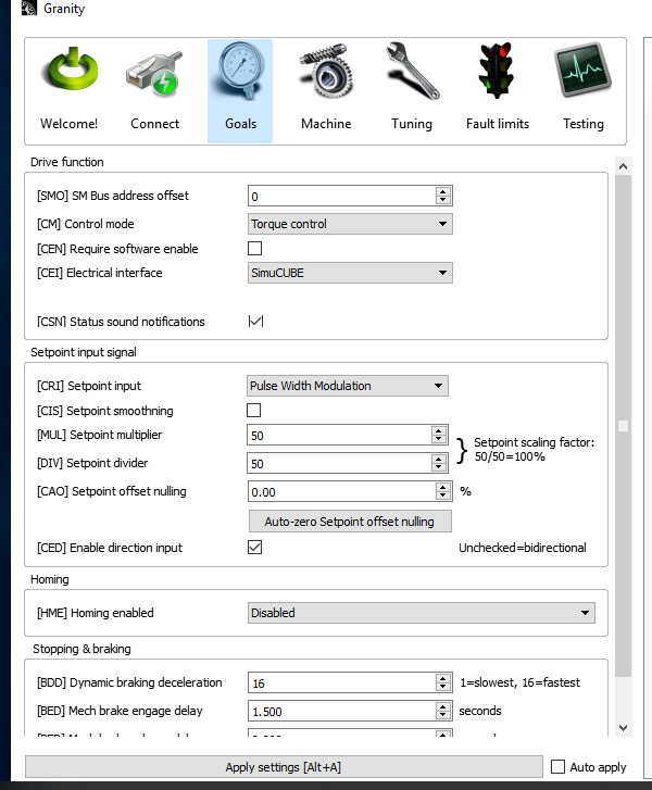
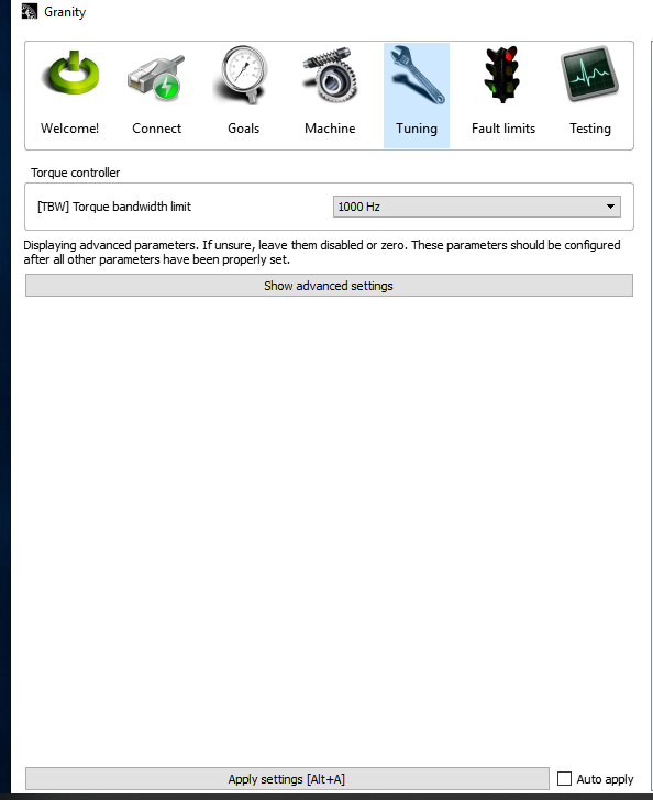
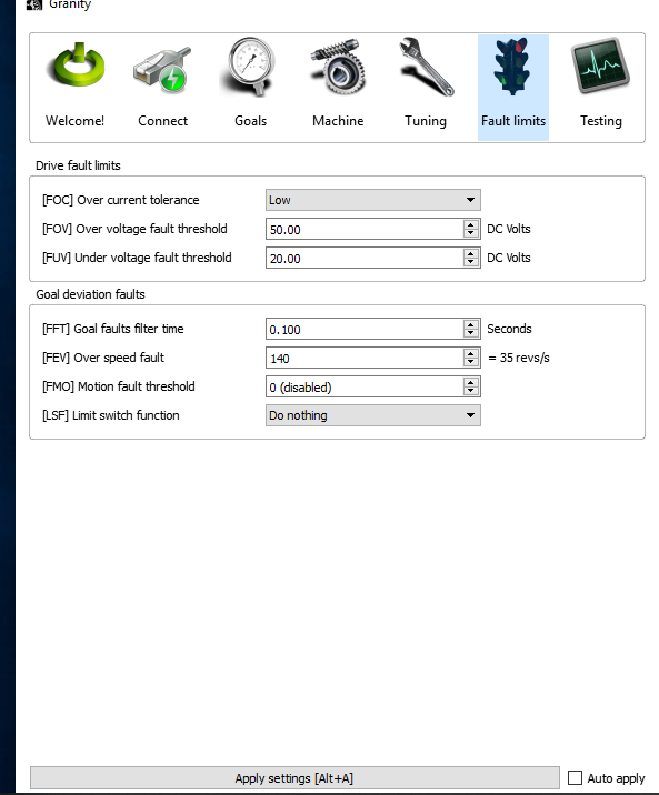
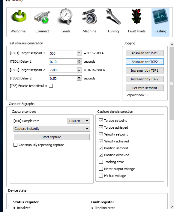
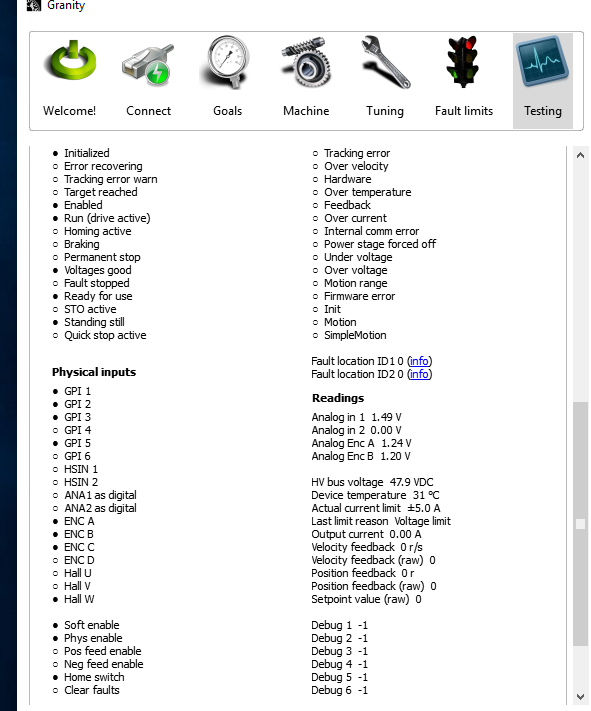
give photos from all the tabs inside granity. also give information about your psu. Aside from those , have you ran Configure motor, encoder and center point ?
He has done the wizard, as it wouldn’t show “Operational” if it has not been run to completion.
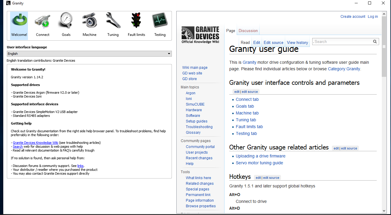
Go to Granity. Observe if the Position Feedback Indication on the Testing tab indicates movement or not.
If not, it is faulty wiring or faulty encoder.
and the wiring / colours on your encoder wire is dependent on where and when you got your encoder. I think Mige supplies wiring with certain colours, that we also have documented somewhere. I’m not at the office now to check things out.
Did you re-run Configure motor, encoder and center point inside simucube tool (next next following the onscreen instructions) ? Does it move in overview ?
w hall pin 12 white
hall v pin 11 grey
hall u pin 10 brown
encoder differential input b- pin 8 green blk
encoder differential input b+ pin5 green
encoder differential input a- pin7 orange blk
encoder differential input a+ pin 4 orange
sv_ out pin 2 red
grd encoder supply pin 3 black
encoder differential input c- pin 9 yellow blk
encoder differential input c + pin 6 yellow
thats how i wired it
and the bare wire i i put the plug outer on the metal as it said to … I was left with 3 wires with no home
Colours mean nothing, as different Suppliers will use different color cables for the encoder plug. You will need to map pin-pin as the diagram Loukas shown above. I used to make my own cables in earlier times, as I used special cabling with emi screen/layer around the signal cables.
So use pin-pin and wire it that way. Same for power-connector.