I just received my Simucube. Can anyone give me help on how to replace my IONI 1x with the Simucube on an Ollie OSW kit?
My hardware configuration:
Ollie / Simplicty “Pre-tested Partially Assembled Direct Drive Wheel Kit (MiGE/IONI)”
Simucube (coming from IONI 1x)
Large Mige 130ST-M15015
Discovery Shield
STM32F4Discovery
IONI Pro HC
10,000 PPR Encoder
Mean Well PSP-600-48
Mean Well RS-25-24
By the way, I have been running my IONI 1x OSW using Granity’s Simucube mode for a year or so, so I have made those 2 slight cable input plug modifications already (in order to run in Simucube mode with the IONI 1x) if that matters.
Discovery Shield
STM32F4Discovery
Mean Well RS-25-24
Those will not be used.
You will move the IONI form the 1x board to the SimuCube and power the SimuCUBE using ONLY the Mean Well PSP-600-48.
The Encoder wiring to the DB15 is exactly the same as the 1x so noting will change there and then the Motor and Estop will be wired into the 7 terminal pheonix connector for the Simucube using the wiring diagram in the wiki… Quick wiring is left to right (Brown, Blue, Black, Empty, Green (Ground), Estop, Estop)
In Granity Change CIE to SimuCUBE mode and basically you should be ready to go.
Seems pretty simple, thanks. I’ve been using Simucube mode in Granity with my non-Simucube setup for a year or so,
I have one concern. I had no idea the Discovery hardware would be removed when going to the Simucube. With the IONI Pro HC and a Large Mige, The 2 5600uF capacitors stored power for use in order to drive the system to more than the 600W PSU could supply this enabling full 27.9 NM of torque with a Large Mige while using only a 600W PSU.
The following may explain it better:
Two elements combine to reduce the PSU requirements.
The Discovery Shield has 2x 5600uF capacitors which store excess electrical energy when the load is below the 12.5A * 1.414 *0.93 = 16.44A peak (Granity value) the PSU is able to supply. The longer the demand periods are for current above 16.44A, the less the capacitors are able to contribute.
Previous calculations are based on a theoretical duty cycle which is far removed from the real-world duty cycle.
The PSP-600-48 is able to drive the large MiGE at 20A+ loads for long enough that IONI Pro HC temperature becomes the factor of concern.
The video below shows the Granity Testing tab of the large Mige and IONI Pro HC combination driven at 20A+ loads over a 6 minute period at Charlotte Oval on iRacing. 6 minutes was the most I could handle at those settings.
So I’m guessing I should be limiting Granity (or Simucube UI settings) to 16.44A unless I get a more powerful PSU?
600 Watts should be enough to drive to the full 27.9Nm with 25A MMC without issue. The servo when set-up generally will only spike to that high of force on a rare occasion with stronger steering cars… Depending on the specific output (at least in iRacing) you may very rarely if ever hit that level…
If it ends up not being capable then every so often you may have the system fault on under voltage every so often (the Large Mige with a 480 Watt Supply does this and the MMC has to be reduced to 23.5A) so if it does you can recreate the issue and lower the MMC to fit OR you can set the MPP to 600 watts and the system will try to predict the wattage draw and make adjustments on the fly. The Large Mige with the SDR 480 doesn’t have any issue at Max but it is nominal 480watt with a 3 second 720 watt Boost.
Basically you will NEVER constantly use maximum power and therefore in most cases will never max out the PSU.
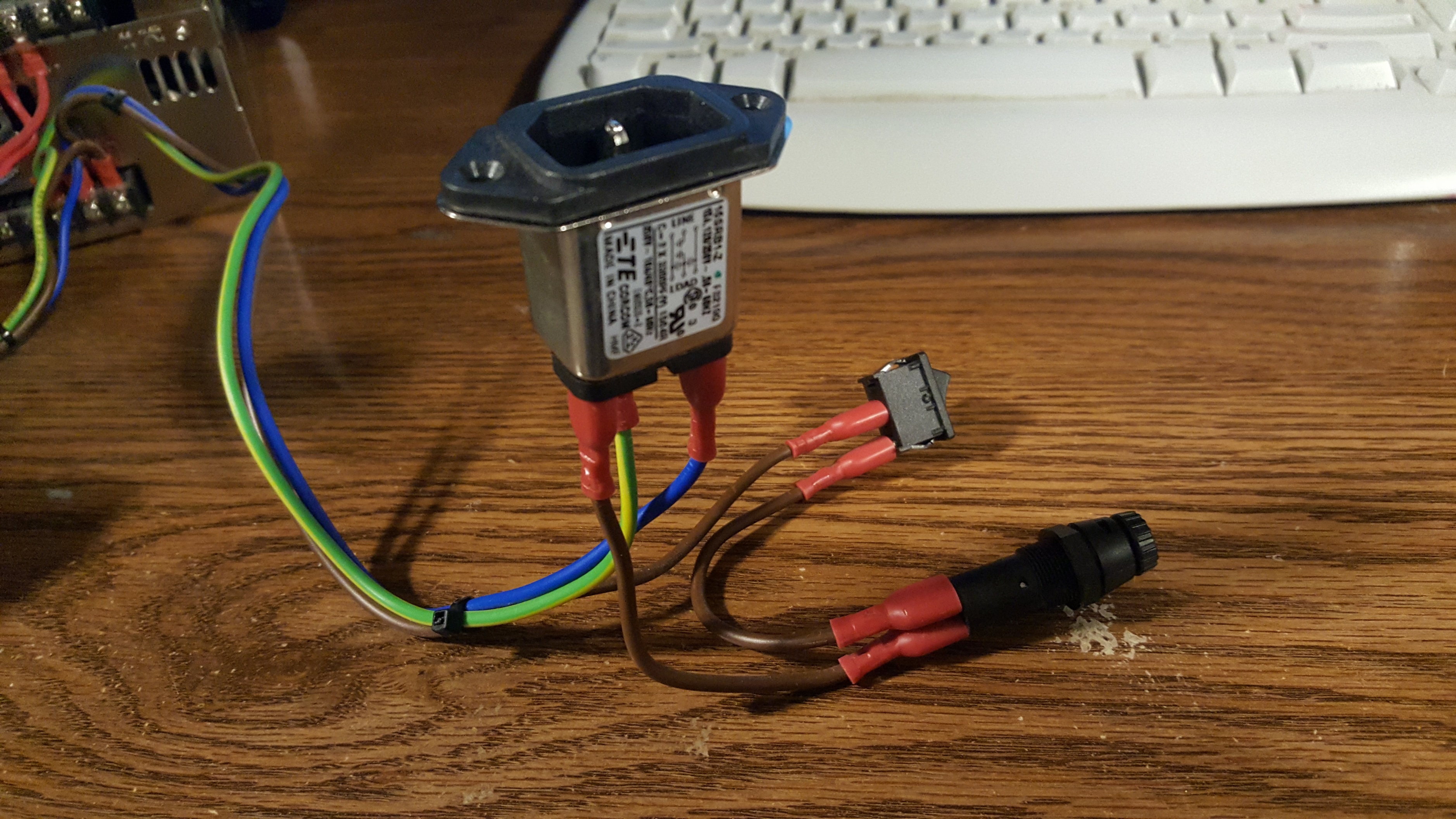
Do I dismantle mine to look like that in the link above or do I keep that extra cylinder thing in the pic below? It seems to be some kind of fuse (says fuse on the top)…
I put the the blue estop cable into the “estop” and the brown e-stop cable into the 5v. Is this correct?
I had a green and yellow ground wire but I can’t take the boot off it at the moment so am temporarily using a red coloured cable for this ground. Both are from my Ollie build. I’m guessing the cables are the same and the colour is only a cosmetic thing? So is it OK to use the red one for now?
Also, is it OK to ground the cable using the hole on the PSU normally used to mount the PSU?
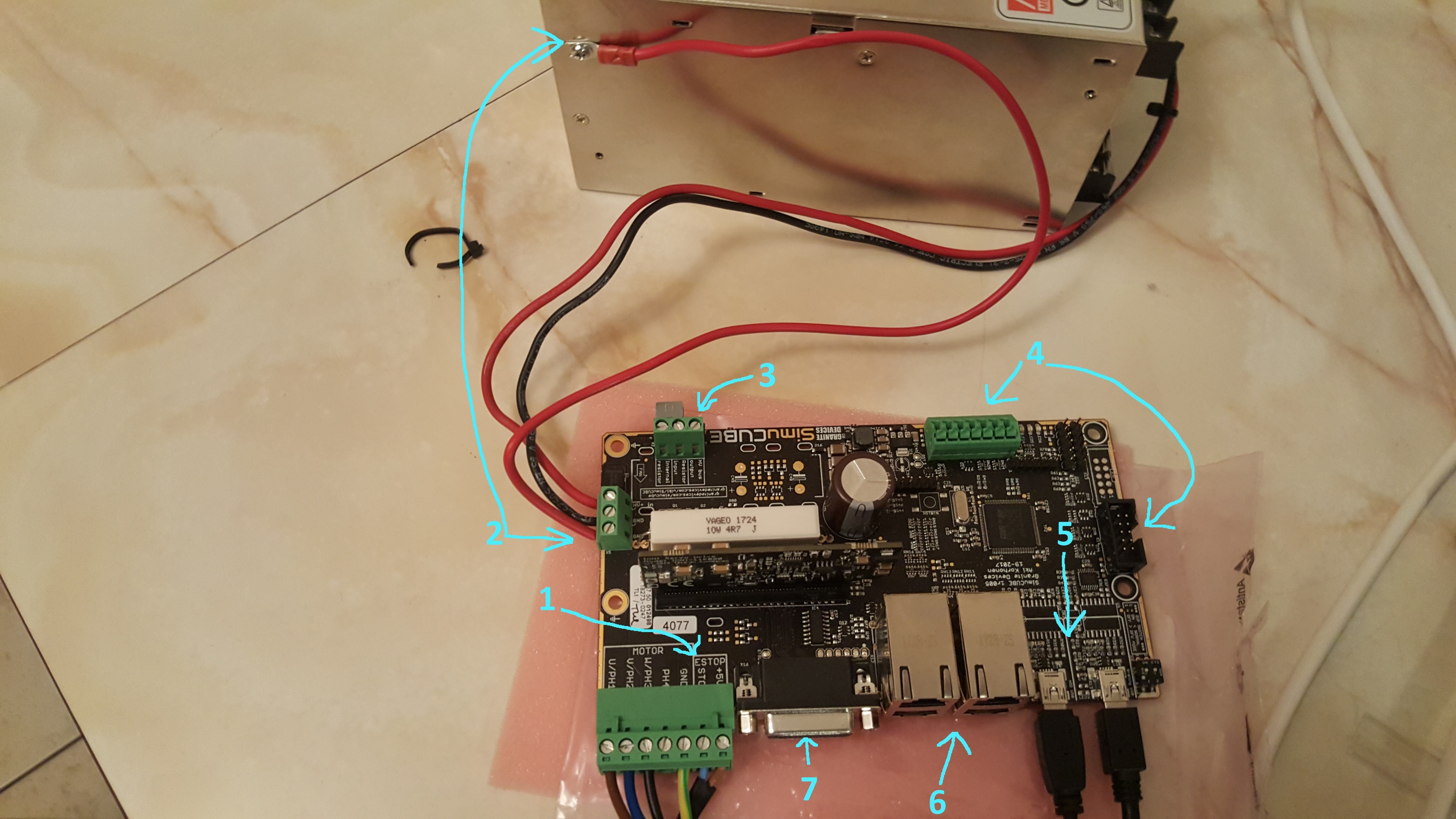
Does anything go in this spot? The first two are taken up by that little metal flap thing but the third is empty. Is it to hook up my braking resistor from my Ollie kit? Is the braking resistor from the Ionicube kit even used at all?
Anything go in here?
One of these is labelled STM32 HID. Isn’t the STM32 the Discovery board/shield which I don’t use anymore? Do I need to use this STM32 HID USB port for anything or only the other USB port?
Do I need to use any of these?
Ignore the fact nothing is plugged in here. I will be plugging the Mige Motor’s encoder cable here.
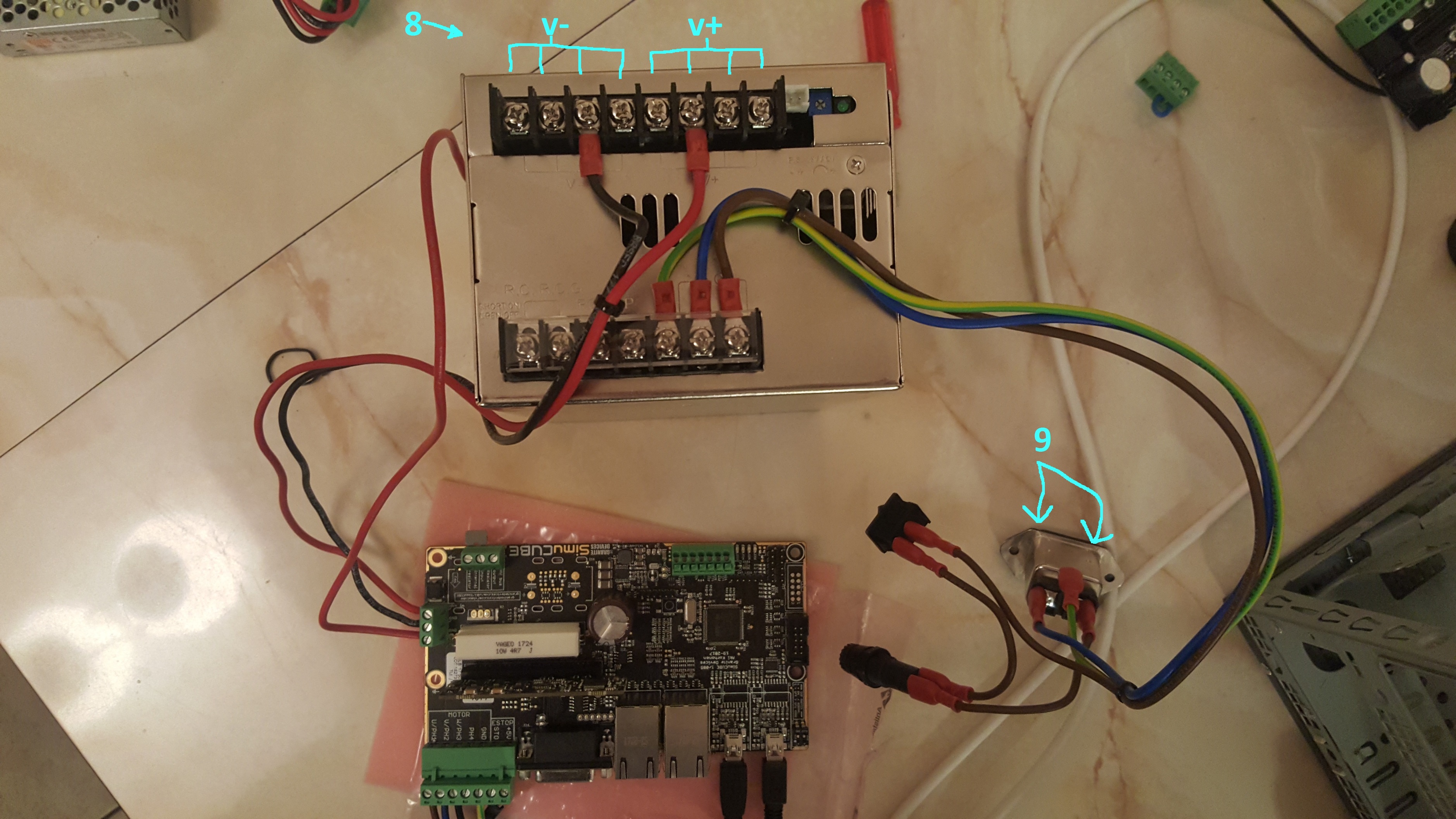
My Ollie kit used 2 v- and 2 v+ slots, is it alright to now use 1 v- and 1 v+?
Does it matter which slots I use?
The blue and brown cables here are switched around in the Granity’s site’s picture I linked to in my previous post. Does this matter? I haven’t changed either end of these cables including how they plug into the PSU. Still setup exactly how they were with my Ollie setup.
You really should use a clearly marked cables for +, - and the protective earth, but it appears you wires are ok if they are similar thickness. Please double check that + goes to + and - to -. It is ok to mount the ground cable like that, if there is no separate grounding outlet in the output terminals of the PSU.
No, that connection is used to connect an external regenerative resistor, but it is not required as SimuCUBE uses the onboard ceramic resistor.
STM32 HID is used for the USB / FFB Interface connection as there is exactly the same processor onboard as you SMT32F4 Discovery board had. The other is used to connect to the IONI drive via Granity.
Great, thanks. Are the cables enough to provide the 600W my PSU is capable of? I don’t know why before my power cable in my Ollie IONI 1x kit used two “+” cables to two “+” ports and two “-” cables to two “-” ports on the psu. Is only 1 of each sufficient?
Going by the pictures above - other than plugging the servo motor encoder into the simucube - am I ready to power this on and start with software/firmware stuff?
The cables look OK. Mainly the issue with too thin cables would be voltage loss over the length of the cable, and thus the IONI drive faulting due to undervoltage. Secondary issue, if very very thin wires are used, would be heating/melting of the cables… I think Ollie just wanted to be extra extra sure by providing double cabling.
It is difficult to know if your DIY is completely ok. Good luck!
I’m trying “Case C” because “Case B” also doesn’t recognize anything but it says that “Case A” should work if the Simucube is new which it is (although the IONI Pro HC is not new), well it’s supposed to be brand new; I purchased it directly from Granite Devices in Finland.
This is all being installed on a fresh Windows 8.1 64-bit install…
EDIT: I just tried “Case C”: turned off power, set both on-board switches to the opposite position (closest to the mini USB ports), powered on. I still don’t see any device in device manager under “universal serial bus controllers” but I do see a STM32 BOOTLOADER under the “other devices” list with a little yellow exclamation mark next to it. I then opened DfuSe Demo but there is nothing listed under “available dfu devices.” What’s going on?
Thanks.
That step isn’t listed in the installation guide just to let you know
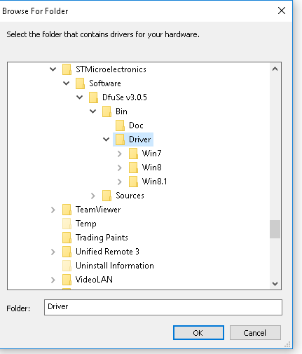
In the driver folder under DfuSe v3.0.5 -> Bin -> Driver -> Win8.1 -> x64, there is only a file with AMD in the name (dpinst_amd64.exe) but I have an INTEL system. Do I still install this file or do I install the x86 file (dpinst_x86.exe)?
I’m using Win 8.1 64-bit with an INTEL 64-bit CPU (Haswell-E i7-5930k)
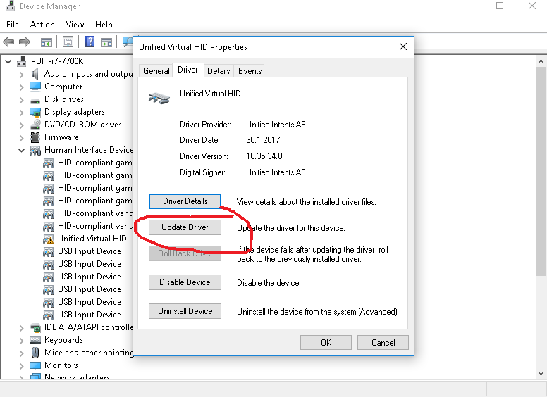
Typically it is enough to point the windows driver update wizard to just the folder where all the drivers are. Windows will install the correct driver automatically.
Driver update wizard can be accessed via the control panel. Note, that this screenshot is for a different device
Thanks, that worked. I did that with “STM32 BOOTLOADER” under the “other devices” list and it worked. The game controller is recognized in the windows controllers section and responds when I turn the steering wheel left and right.
OK, thanks. It’s a little confusing because there is a step by step guide for setting up and installing the simucube so I therefore followed that…I had no idea about the page you referred me to.
In Granity, I’m assuming we’re supposed to use “SimpleMotion USB (FT230X Basic UART)”. Or “SimpleMotion serial port (COM5)?” Both options work and successfully detect the device…
I think the latest Granity version has direct communication to the FT230X uart chip (the first option), and the Serial Com port is the “old” version of the communication method. You can use either one.
OK. I just realized I may have been doing this incorrectly. I would like to use the FFB settings program that allows me to use the new simucube features such as the reconstruction filter. I already converted the hex file and installed the mmos firmware according to the following page: https://granitedevices.com/wiki/Installing_MMos_firmware_into_SimuCUBE. Should I ignore the rest of the SimuCUBE Install Guide (parts 3, 4, and 5 https://granitedevices.com/wiki/SimuCUBE_install_guide) and instead follow the directions in the simucube firmware user guide you linked me to above?
When setting up my motor settings in Granity, are there any settings that differ between using my old setup (Ionicube 1x in simucube mode) and my new setup which is a true simucube setup? Or do I just use the same exact DRC file with no changes?

