Bread board is not strictly necessary. I can connect directly the d15 to the pedsls right?
Not necessary but if no breadboard, you need a cable with 9 wires, and then you will have to solder 3 wires to the same pin (GND and +5v)
My method lets you use a Cat6 lan cable (8 wires) to Connect the breadboard to D15 and use all 8 cables to feed the complete Simucube2 Ecosystem: 4 wires for Axes data pins, 2 wires for Seq, one for +5v and the last is GND
1 Like
Sorry Alfye for noob question: if I make mistakes connecting the cables (invert ground and +5 or others) may I damage the pedals electronic or the SC2?
Be careful with LeoBodnar LC Amp, dont make mistakes with that because you can fry It.
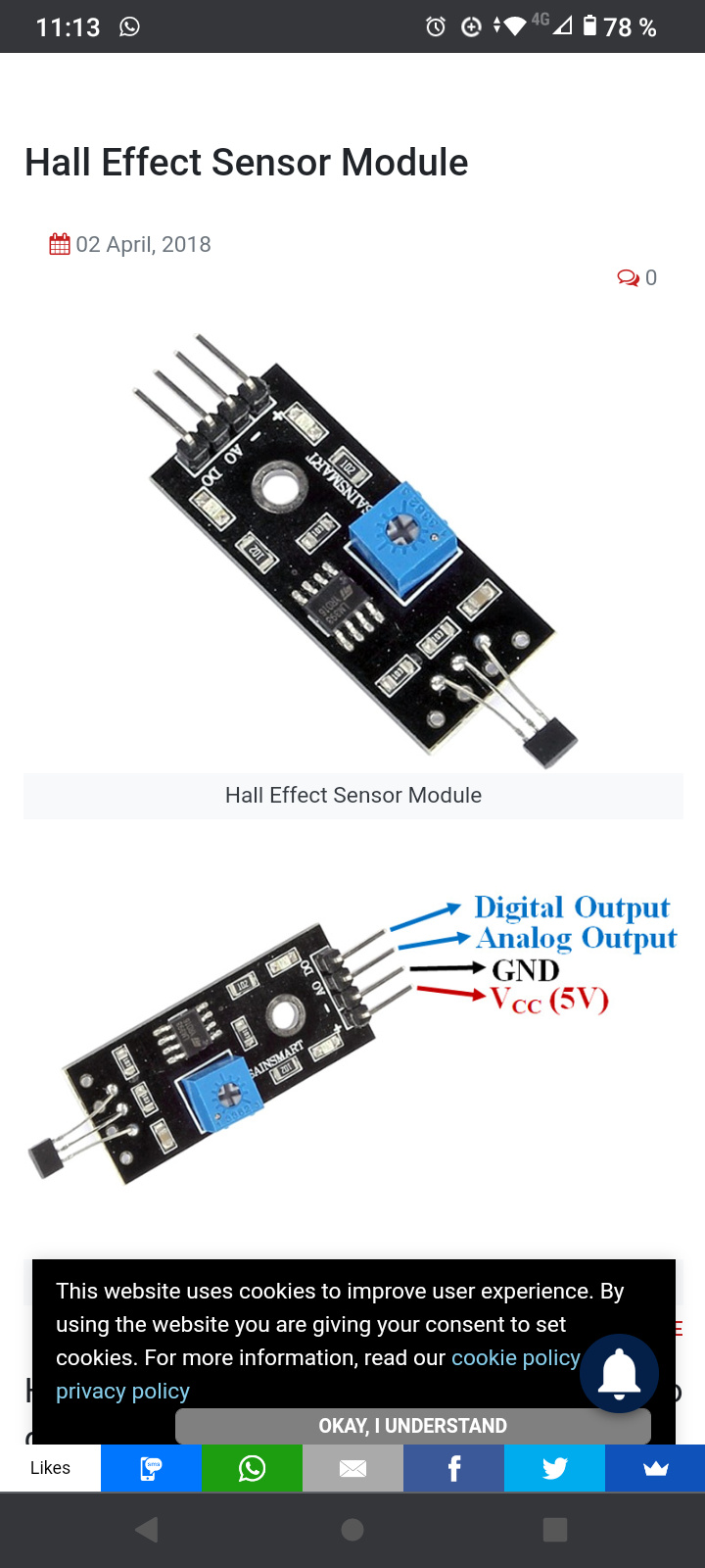
Hall sensors are more forgiving but Data cable must be in place. If you mishmash GND with +5v you will have the signal inverted
Thanks, I have read this from Leo Bodnar site:
“Warning: make sure +5V and GND pins on the potentiometer side are connected correctly!
Load cell is a passive device and wiring mistakes on that side will not damage the amplifier.” maybe this can help me?
LeoBodnar LC Amp has 2 connections sides, one for the 4 wires LC and the other side for SC2 ( potentiometer side)
That text says that be careful when connecting the SC2 to LC Amp because +5v in the wrong pin can damage it
1 Like
So the issue is between SC2 and LC amplifier not between LC and LC amplifier right?
1 Like
Yes, voltage goes from SC2 to LC Amp. LC Amp feeds LC (pasive device) then back to SC2 through GND pin
1 Like
Dear Alfye I have bought a d15 cable and tried to use the buttons only using pin 2 5 and 11, but it does not work. Even if I connect ground and a button there are no results. I have an R2 version, Do I have to do anything to get it to work?
It should work; however button inputs are only processed when Simucube is in the “Operational” mode. Did you maybe have the e-stop pressed in and device had not reached that mode yet?
thanks Mika I have solved I had bad identified the pins, now it works
Dear Alfye I have connected DC V.1 pedals and Heusinkveld shifter without issue. Thank you very much. A friend of mine has got the version 2 of the DC pedals with 4 cables coming from the gas pedal. How does he have to connect it to the base?
1 Like
Just like the brake pedal.
It must be a LoadCell gas pedal
no it is an hall sensor, maybe one of the cables is not used. we are going to try and let you know
A 4 pin hall sensor then…
Can you follow those 4 wires and see where they goes?
Edit, is it like the Pic one?
It was a simple 3 cables hall sensor. One of the wires was disconnencted… it works well now
1 Like
I am also planning to convert my heusinkveld ultimates to simucube via leobondar LC amplifiers
I wonder what is the poll rate and report rate to the pc of the analog ports on SimuCube 2 Pro. I guess its 1000hz, but Simucube staff, please confirm.
Thanks,
Georgi
1000 Hz is absolute maximum on the bus. I do not have the data / usb sniffer logs right now on hand that would tell me how fast it actually is. The analog axises are updated via the same USB packet as the wheel position, so it will certainly be enough.
1 Like
Thanks. That’s what i wanted to hear 
One more question raised. Regarding to max current of 120mA for the 5V output as noted in the documentation. I wonder if I would exceed it when using 3 LC amplifiers and heusinkveld load cells (mavin).
I could not find anywhere in specs the max current for leobondar load cell amplifier.
That probably is also related to particular load cell sensors used, but did not find their max current also.