How would you get the signal out of the HE Sprint brake? I get how you’d do the accelerator and clutch because they have connectors.
BJ Steel GT pedals (2 hall sensors + 200kg loadcell) directly to SC2 accesory Port is working as It should.
LC sensor has 4 wires so LeoBodnar LC Amp is needed.
Hall sensors without problems.
Full Simucube 2 Ecosystem:
Edit:
I Saw some Heusinkveld Sprint photos on its webstore and looks like the LC sensor is a 4 wires one like the BJ Steel ones, so you need to follow those cables and look at where It connects on the integrated PCB. Try to disconnect or desolder to not damage/devaluate your pedals. Or cut at a reasonable lenght:
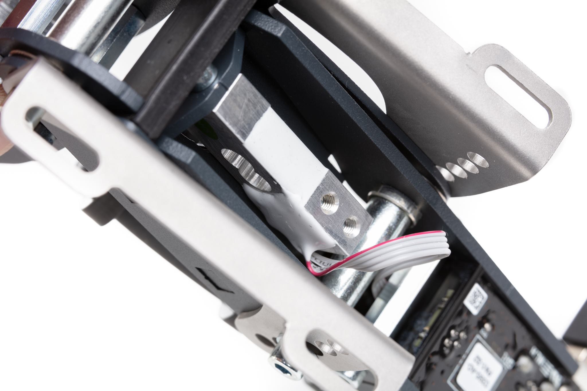
Connect those 4 wires to Leo Bodnar LC amp.
Dont Know about gas/clutch on Sprints, are they hall sensor or LC?
3 Likes
All 3 pedals are LC.
So 3 LeoBodnar LC amps are needed to run the Sprints directly onto SC2 base
The DC simracing pedals are 2 hall sensor and a LC. It would be quite easy to connect them?
Sure!
Just like the BJ pedal.
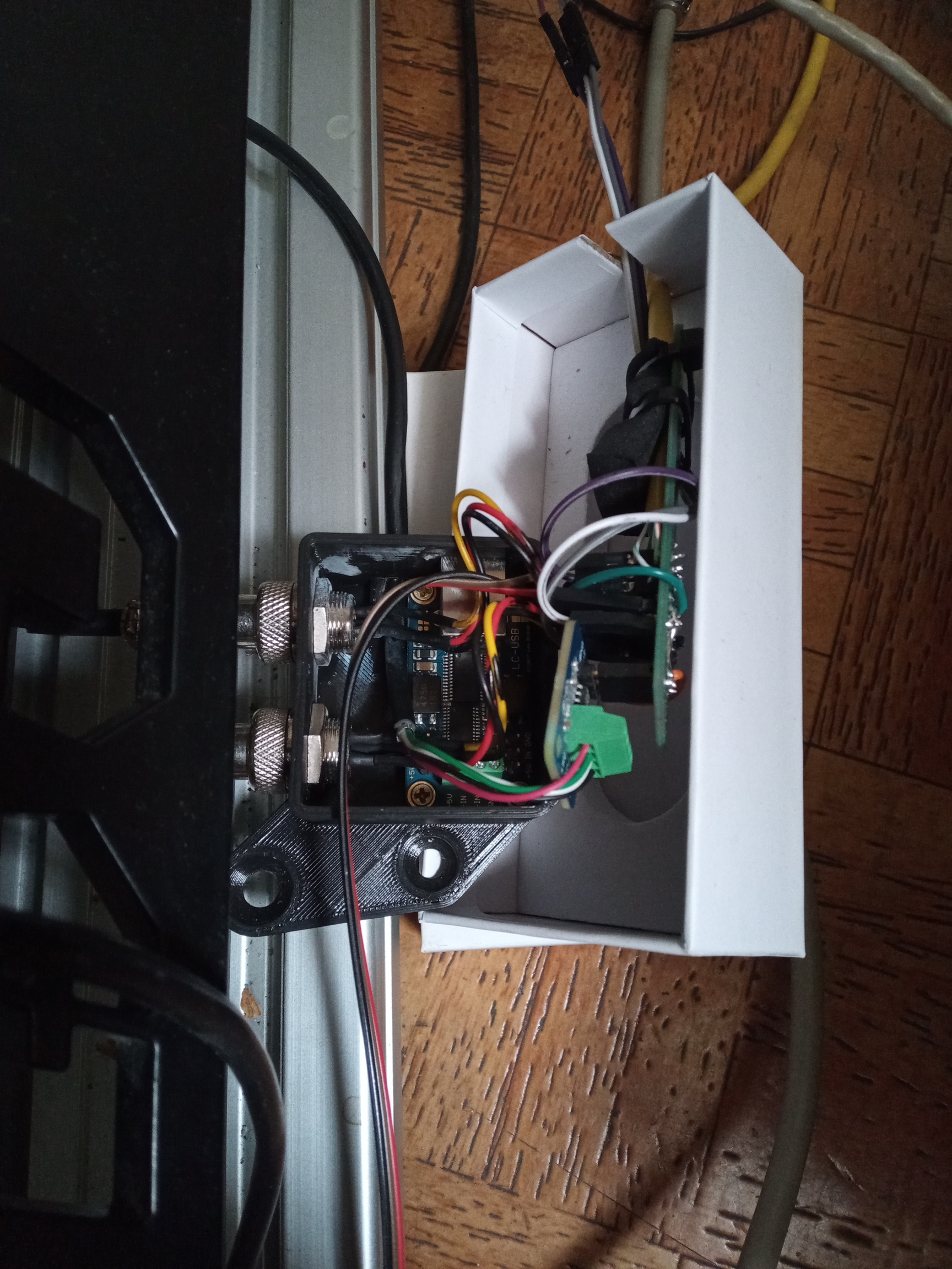
I was able to maintain the OG PCB box doing some jumps and a middle connections board. It is a mesh but I will take care of It soon
2 Likes
you are fantastic thank you
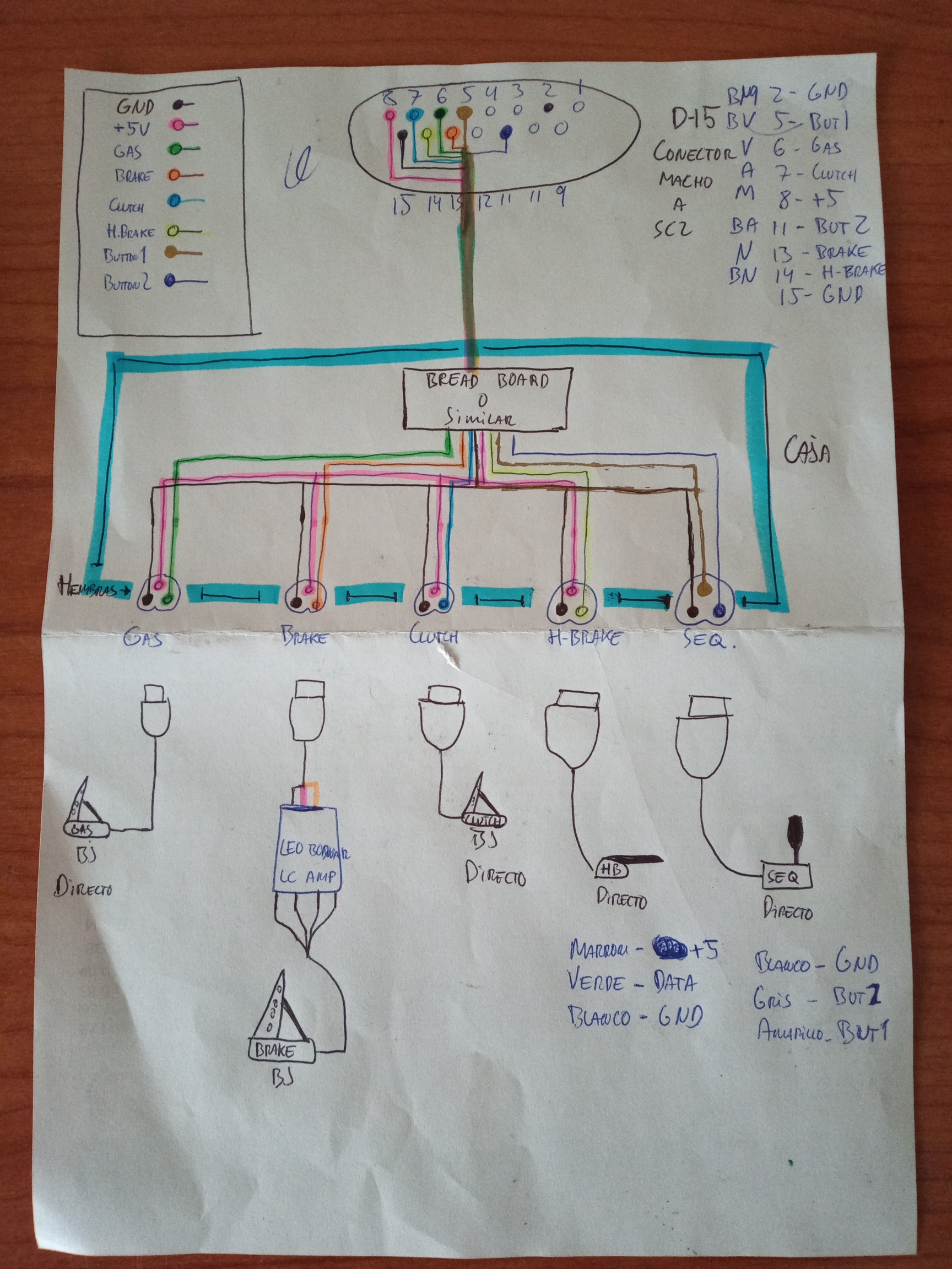
Bread board is not strictly necessary. I can connect directly the d15 to the pedsls right?
Not necessary but if no breadboard, you need a cable with 9 wires, and then you will have to solder 3 wires to the same pin (GND and +5v)
My method lets you use a Cat6 lan cable (8 wires) to Connect the breadboard to D15 and use all 8 cables to feed the complete Simucube2 Ecosystem: 4 wires for Axes data pins, 2 wires for Seq, one for +5v and the last is GND
1 Like
Sorry Alfye for noob question: if I make mistakes connecting the cables (invert ground and +5 or others) may I damage the pedals electronic or the SC2?
Be careful with LeoBodnar LC Amp, dont make mistakes with that because you can fry It.
Hall sensors are more forgiving but Data cable must be in place. If you mishmash GND with +5v you will have the signal inverted
Thanks, I have read this from Leo Bodnar site:
“Warning: make sure +5V and GND pins on the potentiometer side are connected correctly!
Load cell is a passive device and wiring mistakes on that side will not damage the amplifier.” maybe this can help me?
LeoBodnar LC Amp has 2 connections sides, one for the 4 wires LC and the other side for SC2 ( potentiometer side)
That text says that be careful when connecting the SC2 to LC Amp because +5v in the wrong pin can damage it
1 Like
So the issue is between SC2 and LC amplifier not between LC and LC amplifier right?
1 Like
Yes, voltage goes from SC2 to LC Amp. LC Amp feeds LC (pasive device) then back to SC2 through GND pin
1 Like
Dear Alfye I have bought a d15 cable and tried to use the buttons only using pin 2 5 and 11, but it does not work. Even if I connect ground and a button there are no results. I have an R2 version, Do I have to do anything to get it to work?
It should work; however button inputs are only processed when Simucube is in the “Operational” mode. Did you maybe have the e-stop pressed in and device had not reached that mode yet?
thanks Mika I have solved I had bad identified the pins, now it works
Dear Alfye I have connected DC V.1 pedals and Heusinkveld shifter without issue. Thank you very much. A friend of mine has got the version 2 of the DC pedals with 4 cables coming from the gas pedal. How does he have to connect it to the base?
1 Like
Just like the brake pedal.
It must be a LoadCell gas pedal