I am posting here to check whether we are on the right path. The object is to modernise an old 1960’s Beaver Mill. We rescued it over ten years ago and computerised it by building new driver cards for the old unipolar steppers and controlling it with Mach3, but now, 10 years later, we would like to improve further.
Unipolar steppers have their issues and so does Mach3, especially on modern hardware. So the owner has bought three servo motors:
So this is what we intend to add:
Hardware
Three Granite Argon Cards
One SimpleMotion V2 USB adapter
One 24V PSU for logic Estop and brakes (how much power is needed?)
One computer
This takes care of the hardware bit. Does this bit sound OK?
Software
This is the tricky part. The easiest path is probably Mach4 pro, but LinuxCNC looks very tempting. Anyway, the setup above should work with either Mach4 or LinuxCNC, right?
Those servo motors looks to be very ideal to Argon.
Argon is specified at maximum of 0.5 A for the 24 V logic voltage, so you should be able to estimate the current needed from checking the motor brake current consumption. Also, it’s usually good practice to add some overhead to the PSU powre rating. This especially so if cheapest Chinese PSUs are used, as they tend to be overrated very often.
For the setup, I recommend you get also a good braking resistor and a simplemotion breakout board (SMV2BRK). The latter makes the termination and wiring a breeze. https://granitedevices.com/wiki/SMV2BRK
Both Mach and linuxcnc will work well with your setup. Easiest being step/dir setpoint signal for which many interface cards are available.
An additional question: We cannot find any mention of how much power the brake needs from 24V. I guess you can hook up a LAB PSU to the brake and measure?
Step/dir refers to two signals, step being the signal to tell the drive to move the motor one step, dir giding the direction of the move.
Originally used with stepper motors, which are controlled via steps, but nowadays also servo motors where the step is one encoder pulse. If the servo drive is used in position mode, the controller software doesn’t necessarily have to have feedback from the encoders, as with stepper motors when used without encoders. In this scenario, step/dir control method is about the easiest possible, and there are a lot in interfaces available.
In this case there will be servo motors, with encoders, to abolutely make sure that we never lose the position. This is the reason for going from the old motors to servo.
So, that makes the parts list:
Hardware
Three Granite Argon Cards
One SimpleMotion V2 USB adapter
One SimpleMotion breakout board SMV2BRK
One 24V PSU for logic Estop and brakes (Need to measure the servo motor brake resistance)
One computer
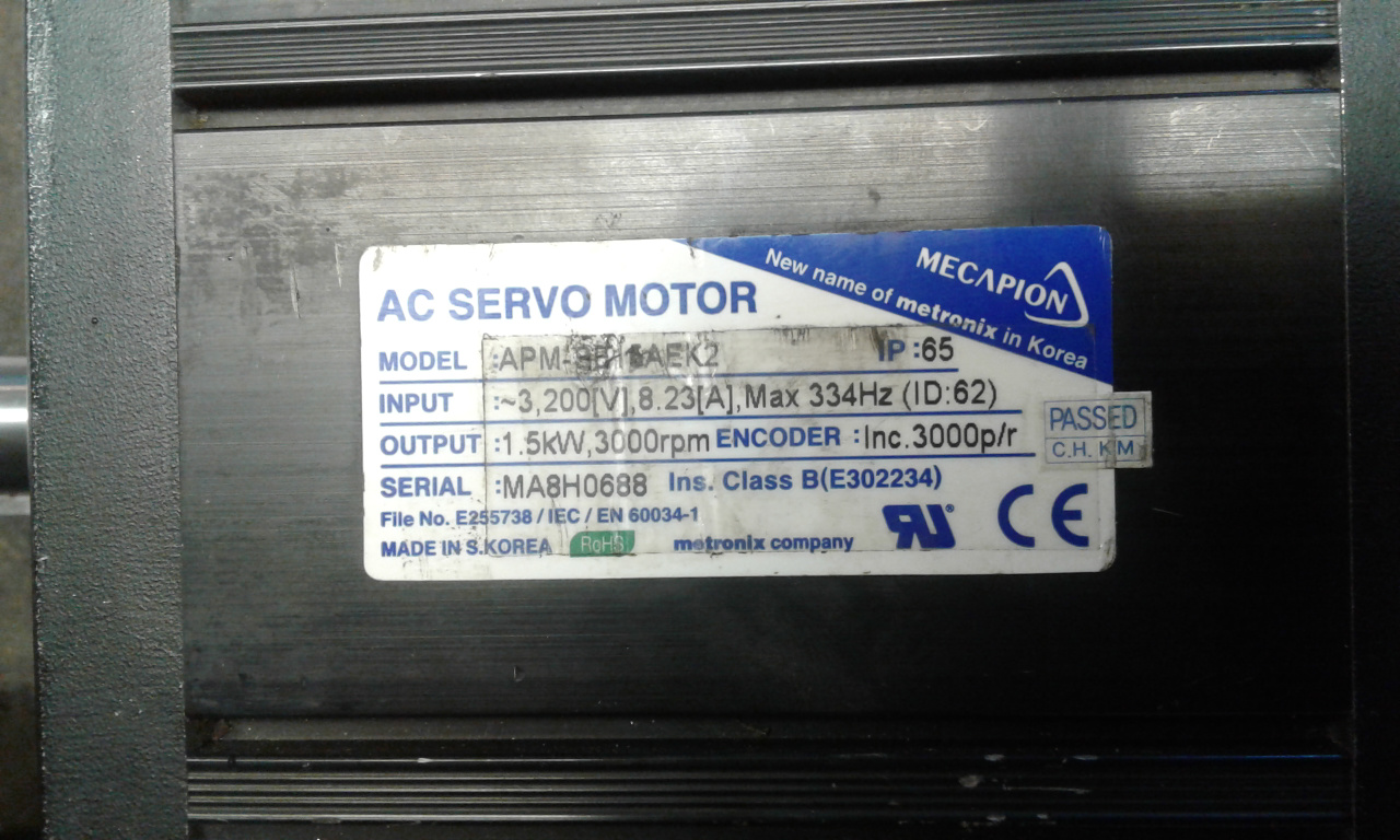
 So if the brake is a pure resistive device, then I could just measure the resistance and calculate the power from that. Right?