Ok I understood the use of the 7 pin.
The problem is that because I want to use the shifter, some buttons can’t move…
Maybe it would have been possible to only have 7 pins to move…
Below is the current code. You can enable and disable easily buttons with the enabledButtons[]. You can only use 7 buttons.
The current code :
// Initial work by Jason Duncan to adapt G27 shifter and pedals on an arduino. (G27_Pedals_and_Shifter.ino)
//
// Modified by Lebois so we can plug the g27 shifter into the simucube.
// you can only use 7 buttons, so I choose to desactive the upper buttons, and one red button.
// Partially adapted from the work done by isrtv.com forums members pascalh and xxValiumxx:
// http://www.isrtv.com/forums/topic/13189-diy-g25-shifter-interface-with-h-pattern-sequential-and-handbrake-modes/
#include <Wire.h>
#include “Adafruit_MCP23017.h”
Adafruit_MCP23017 mcp;
// Set to 1 to enable one button. You can only use 7 buttons.
int OUTPUT_RED_CENTERRIGHT = 0 ;
int OUTPUT_RED_CENTERLEFT = 1;
int OUTPUT_RED_RIGHT = 1;
int OUTPUT_RED_LEFT = 1;
int OUTPUT_BLACK_TOP = 0;
int OUTPUT_BLACK_RIGHT = 0;
int OUTPUT_BLACK_LEFT = 0;
int OUTPUT_BLACK_BOTTOM = 0;
int OUTPUT_DPAD_RIGHT = 1;
int OUTPUT_DPAD_LEFT = 1;
int OUTPUT_DPAD_BOTTOM = 1;
int OUTPUT_DPAD_TOP = 1;
int enabledButtons[] = {
// first four are unused
0, 0, 0, 0,
OUTPUT_RED_CENTERRIGHT,
OUTPUT_RED_CENTERLEFT,
OUTPUT_RED_RIGHT,
OUTPUT_RED_LEFT,
OUTPUT_BLACK_TOP,
OUTPUT_BLACK_RIGHT,
OUTPUT_BLACK_LEFT,
OUTPUT_BLACK_BOTTOM,
OUTPUT_DPAD_RIGHT,
OUTPUT_DPAD_LEFT,
OUTPUT_DPAD_BOTTOM,
OUTPUT_DPAD_TOP
};
// SHIFTER PINS
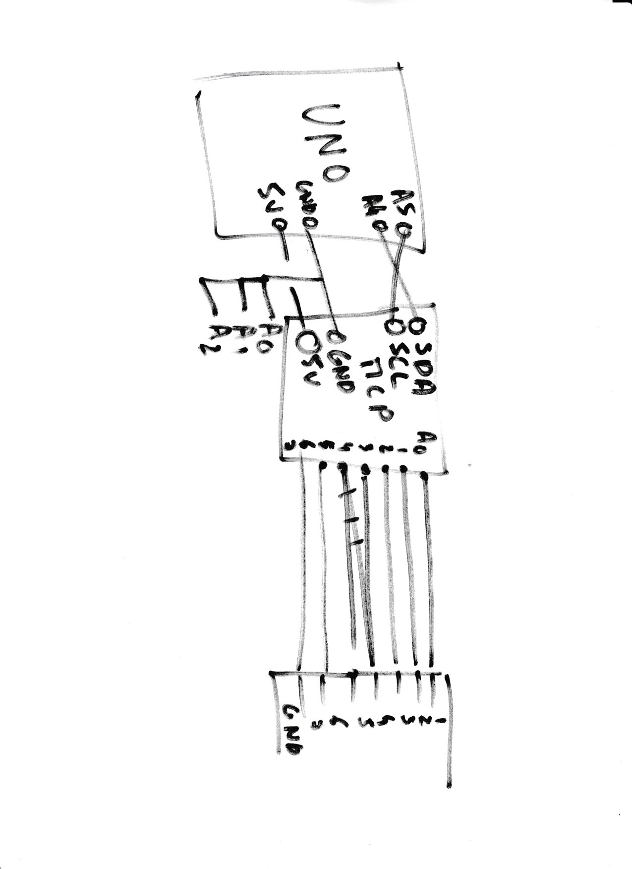
//| DB9 | Original | Shifter | Description | UNO |
//| 1 | Purple | 1 | Button Clock | pin 10 |
//| 2 | Grey | 7 | Button Data | pin 11 |
//| 3 | Yellow | 5 | Button !CS & !PL (Mode) | pin 9 |
//| 4 | Orange | 3 | Shifter X axis | pin 1 (A2) |
//| 5 | White | 2 | SPI input | |
//| 6 | Black | 8 | GND | GND |
//| 7 | Red | 6 | +5V | VCC |
//| 8 | Green | 4 | Shifter Y axis | pin 0 (A4) |
//| 9 | Red | 1 | +5V | VCC |
#define SHIFTER_CLOCK_PIN 10
#define SHIFTER_DATA_PIN 11
#define SHIFTER_MODE_PIN 9
#define SHIFTER_X_PIN 1
#define SHIFTER_Y_PIN 0
// BUTTON DEFINITIONS
#define BUTTON_REVERSE 1
// SHIFTER AXIS THRESHOLDS
#define SHIFTER_XAXIS_12 350 //Gears 1,2
#define SHIFTER_XAXIS_56 670 //Gears 5,6, R
#define SHIFTER_YAXIS_135 700 //Gears 1,3,5
#define SHIFTER_YAXIS_246 400 //Gears 2,4,6, R
#define SIGNAL_SETTLE_DELAY 10
void waitForSignalToSettle() {
delayMicroseconds(SIGNAL_SETTLE_DELAY);
}
void getButtonStates(int *ret) {
digitalWrite(SHIFTER_MODE_PIN, LOW); // Switch to parallel mode: digital inputs are read into shift register
waitForSignalToSettle();
digitalWrite(SHIFTER_MODE_PIN, HIGH); // Switch to serial mode: one data bit is output on each clock falling edge
for(int i = 0; i < 16; ++i) { // Iteration over both 8 bit registers
digitalWrite(SHIFTER_CLOCK_PIN, LOW); // Generate clock falling edge
waitForSignalToSettle();
ret[i] = digitalRead(SHIFTER_DATA_PIN);
digitalWrite(SHIFTER_CLOCK_PIN, HIGH); // Generate clock rising edge
waitForSignalToSettle();
}
}
void getShifterPosition(int *ret) {
ret[0] = analogRead(SHIFTER_X_PIN);
ret[1] = analogRead(SHIFTER_Y_PIN);
}
int getCurrentGear(int shifterPosition[], int btns[]) {
int gear = 0; // default to neutral
int x = shifterPosition[0], y = shifterPosition[1];
if (x < SHIFTER_XAXIS_12)                // Shifter on the left?
{
  if (y > SHIFTER_YAXIS_135) gear = 1;   // 1st gear
  if (y < SHIFTER_YAXIS_246) gear = 2;   // 2nd gear
}
else if (x > SHIFTER_XAXIS_56)           // Shifter on the right?
{
  if (y > SHIFTER_YAXIS_135) gear = 5;   // 5th gear
  if (y < SHIFTER_YAXIS_246) gear = 6;   // 6th gear
}
else                                     // Shifter is in the middle
{
  if (y > SHIFTER_YAXIS_135) gear = 3;   // 3rd gear
  if (y < SHIFTER_YAXIS_246) gear = 4;   // 4th gear
}
if (gear != 6) btns[BUTTON_REVERSE] = 0; // Reverse gear is allowed only on 6th gear position
if (btns[BUTTON_REVERSE] == 1) gear = 7; // Reverse is 7th gear (for the sake of argument)
return gear;
}
void setup() {
// Serial.begin(9600);
mcp.begin();
pinMode(SHIFTER_MODE_PIN, OUTPUT);
pinMode(SHIFTER_CLOCK_PIN, OUTPUT);
digitalWrite(SHIFTER_MODE_PIN, HIGH);
digitalWrite(SHIFTER_CLOCK_PIN, HIGH);
for (int i =0; i < 16; i++){
mcp.pinMode(i,OUTPUT);
}
}
void loop() {
int buttonStates[16];
getButtonStates(buttonStates);
int shifterPosition[2];
getShifterPosition(shifterPosition);
int gear = getCurrentGear(shifterPosition, buttonStates);
setGearState(gear);
setButtonStates(buttonStates);
delay(50);
}
void setGearState(int gear){
for (int i =0; i < 7; i++){
mcp.digitalWrite(i, HIGH);
}
if (gear >0){
mcp.digitalWrite(gear-1, LOW);
}
}
void setButtonStates(int buttons[]) {
int c=0; //c is here to check that we only use MCP B0 to B6
for (int i = 0; i <= 15; ++i) {
if((buttons[i]==1)&&(enabledButtons[i]==1)){ //if button is high and enabled, output
mcp.digitalWrite(c+8, LOW);
c=c+1;
}
if((buttons[i]==0)&&(enabledButtons[i]==1)){ //if button is low and enabled, no output
mcp.digitalWrite(c+8, HIGH);
c=c+1;
}
}
}