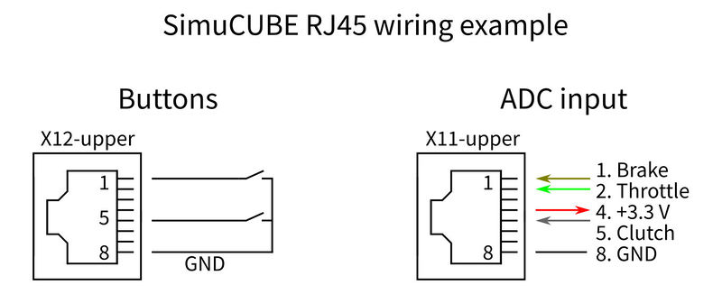
I’m trying to hook up an old G27 brake pedal using the X11-upper port. I think I have understood the wiring diagrams correctly, though I’m not having any luck getting it configured. The image below shows how I have linked up the potentiometer to the cable.
When I go to the configure analog inputs tab in the Simucube software, and enable the pedal, the raw value hovers around 14-17. But when I compress the pedal, the raw value increases but is not stable. It will spike everywhere between the compressed and uncompressed value. I have tried ground the +5v tab of the potentiometer to the metal casing of the pedal, and grounding the pedal to the simucube base/electronics unit. But none of these seem to make any difference. Could anyone guide me as to what I’m doing wrong?
Yeah something is up with the cable. Just compared it to another one and it’s different. Didn’t order a crossover cable but looks like that’s what I got!
Thanks. This means actually not dangerous on X12 because there is no supply voltage? And on X11 Pin 4 and 8 shouldn’t be connected together by any means? Sorry, I am not a technician.
Correct, no issue on X12, as all inputs are pulled low when active. But X11 a problem because of supply voltage and ground pins, like Mika said, if you short the Vreg, it can burn out after a short period of time.
So when wiring a pot for throttle and brake, does on side of pot go to 3.3v, the other side go to ground, and the wiper go the to ADC input? @Mika@phillip.vanrensburg
Mika, thanks, but I have seen that page many times and it doesnt really show an example of how to wire a pot, and what the correct values of a pot would be. I think I have a 10k, and connected +3.3v, and gnd to the outside of the pot and used the wiper, and connected it to the wiper of the pot.
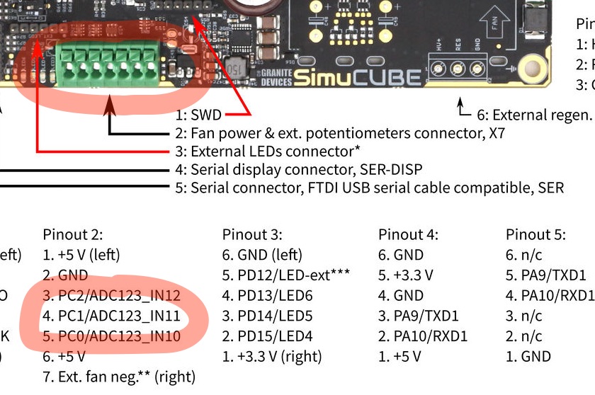
You need to connect ground to one extreme of the pot. and +5v to the other extreme of the pot. then, the connection in the midde must be connected to the ananlog inputs PC0, PC1 and PC2. All you need is already in the BIG GREEN connector in the motherboard. Here is the relevant information with some marks.