Dear Community good afternoon from Italy!
With this message and topic I deeply hope that i will be able to help a friend that is facing a problem with his Simucube 1.
After a short circuit that damaged the PC motherboard, also the Simucube 1 is no longer recognized as a controller (but is still saw from PC as a COM port). The wheel startup routine till “ok beep” are working too.
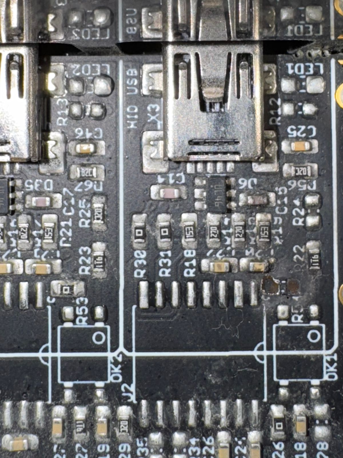
Following the guidance of the troubleshooting page he checked the USB ESD protection diodes. He measure 600 Ohms between GND and one pad, infinite on the other, so he assume the ESD chip shall be replaced (on X4 port, undamaged, he measure infinite on both).
Beside this, as you see in the attached picture, another component [R51] literally blew up and is missing. He suspect R20 as well is damaged. Can you provide a schematic/list of component of this part in order to have it checked and, possibly, repaired?
thanks a lot!!
Ema