Hello!
I have a plan of retrofit of an old milling machine cnc. All the equipment which I have for that are new. I am at the stage or I must find resistance MR and inductance ML. Except that it is impossible for me to make turn the engine because I have errors which I do not understand in the software granity.
My hardware configuration:
Argon
SimpleMotion V2 USB adapter
Last 2.1.2 frimware
Logic supply from granite shop : RS-25-24, 25 W 24 VDC power supply
Old french servomotor permanent magnet (Couple 8 n.m, courant 12.8A, KT 0.64 n.N/A, KE 67 V/1000tr/mn, speed max 2700 tr/min, max voltage 200V)
The principal error looks to be under voltage. I checked with the multimeter on argon terminals, I have well 24V DC logic suply and 230V AC line supply
On these photos the Ethernet cable is not connected. I do not use either the resistance of brake for the moment. I did not add the magnet either (I receive them this week)
(I can’t add more than one photo for now )
It seems to me that I had the same errors before connecting the engine and 230V line. From where can these problems they occur?
Ok thank you for your fast return. I am really a noob. I had believed to understand that the breakout was only in the case of use of E stop.
I have just ordered SimpleMotion V2 breakout board. While waiting to receive it, I will use the fast method. (A quick’n’dirty way to make enable drive & disable safe torque off connection. May be used for testing before final wiring)
For the engine, it is not a brushless it is an error of my share. It is well an engine DC I have only two wire to feed it.
Thank you very much for your help, I keep you informed if I have new faults.
Hello. I do not have any more errors, I succeeded in making turn my engine yesterday evening! I must just check my rotary encoder, it is not completely ok yet.
I have a question concerning the power supply of the servomotors. It is noted on the plate that the voltage max is of 200V. As the engine is an engine DC, I imagine that corresponds to Max 200VDC for each servomotor.
For now I feed argon with 230VAC, which gives approx. 300VDC, which is too high for my engines.
The best solution is it to use an auto-transformer to reduce the tension of entry to 120VAC on argon to have 200VDC max on the level of my engines? Or I could do something on Argon?
A servo drive is the device to control the output voltage to the motor so that required torque is achieved. When torque mode is tuned properly, then from the feedback device data, position and velocity control can be controlled.
Hello! Indeed the 230 VAC looks to pass well thank you for your assistance! This weekend, I roasted two of my Argons: ( I think that the J5 port did not appreciate the alimentation of 24VDC for my switch and home (however indicated in documentation). I would have to test 5VDC before
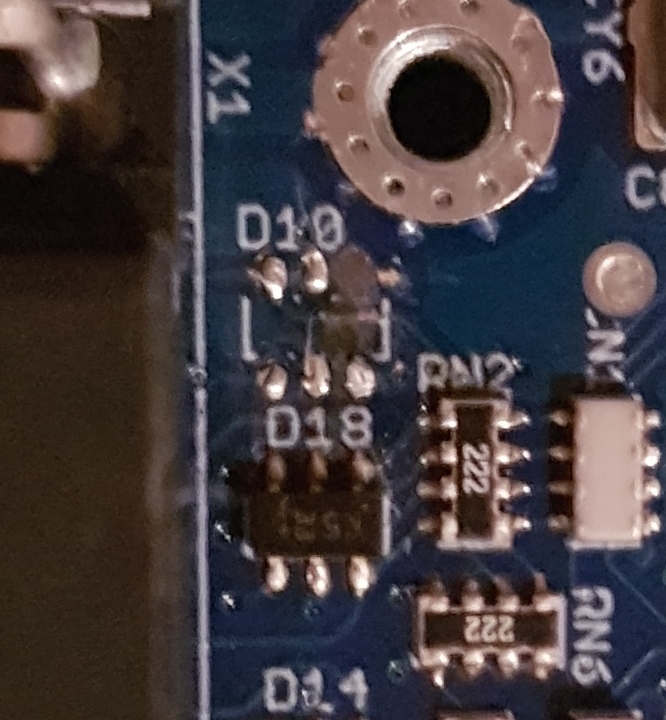
I dismounted them and by chance, it is the security component D10 with 6 legs which looks to have fry. As this component is similar to D19 I followed the instructions of your site: “Determining_Argon_hardware_failure”
I ordered yesterday 15 components PESD5V0S4UD for replace my D10 as well as component SN65176BDR in the doubt. I also bought a hot air soldering station as indicated.
Edit : is it possible to have the reference of the SMV2BRK green 2amp fuse?
For my first argon I also thought that came from the J1 port. Therefore to test, I did not connect J1 on the second argon. I connected only J5 and that still roasted… However on my first argon my switch and home were indicated correctly in the test part. When I actuated them, the indicators in the test part of granity were ok.
For J5 I followed the diagram of documentation but I think of having understood the error. I would not have to follow the exact diagram and to connect in 24V external… I connected in 24V on the pine 2 which joined then the pine 20 - 22 - 24 whereas it is an exit 5V T_T
I received equipment to be able to make the change of the components but I have just noticed that two other components had burned on one of my argons. They are the components with 3legs D4 and D6. Can I please have also the reference of these components if possible?
Concerning my milling machine I am in a dilemma concerning a technological choice. As previously indicated, my 3 servo motors have a rotary encoder fixed in the back.
I have just laid hands on the originals rules of positioning of the machine: They are linear scale Heidenhain LS 403 of an accuracy of 3 to 5microns.
I saw that the new frimware integrated the management of Sin/Cos signal I can thus put them in closed loop by the J5 port if I understood well.
What do you think about it, I must keep my rotary coders on the J3 port and the rules in J5 the whole in closed loop? Will the rotary coders be useful for the swiftness and the torque where as the rules are useful for the position?
Sorry to hear about burned components. D4 and D6 have type of ESD24VS2UE6327, they are overvoltage protection diodes on enable and STO inputs. So it is likely that wiring error has burned them.
I received components ESD24VS2UE6327 of replacement, I think of succeeding in replacing them. However, I do not think of succeeding
concerning the D10 component. While wanting to remove the defective component, a small portion of the PCB came with what largely complicates repair with my skills. Is it possible to make working Argon without the security component D10?
Concerning the connection of my linear scales on the J1 port, there are only two channels sin/cos (A and B) whereas my Heidenhain connector to 9 pine has 3 channels (l1, green, yellow/l2, blue, red/l0, Gray, pink/5V brown/0V white and shield, white-brown). How do I have to proceed concerning the connexion?
Could you be a bit more specific, what did you mean with the “small portion of the PCB came”? Did some copper trace peel off the PCB?
I was unable to find the datasheet for the LS-403 to check for the wiring. Can you provide one?
Please note, that it’s not recommended to use only a linear encoder with a rotary motor. Any play in the mechanics, the torsion of the screw, and any other non-ideality can result in oscillation to the system (depending on tuning), and could cause damage.
I would like to share you few photos but I am limited to only one picture at the same time, it is rather constraining. I am forced to remove my previous pictures to display news of them, if it is possible to free that, that would be marvellous ^^ Here is a photo of my D10 compenant’s PCB part :
If it’s not recommended to use only linear encoder how I can do? In fact my servo-motors have an integrated tachometer. There are also rotary coders heidenhain in the back. I have also these 3 rules heindenhain. The controller board that I use (eding cnc, cpu5B) work in open loop. I cannot use two close loop as indicated on the document of Tero.
My machine is a Aciera F35, manufactured in Switzerland. All the mechanical parts are in perfect condition, I do not think that there will be problem because the original machine functions like this.