I need to order new NDR-480 and think how i will secure it to case so that i do not make same mistake i did with blown up PSU. Attachment screws were too long in one hole and they were shortcircuiting one transsistor which caused shortcircuit in PSU. Bummer but good that it was only 100 euro lesson.
Yes you have to be careful of length of screw you use to mount the power supply if not using the din rail.
And most everyone who built SC1 with the MW NDR or SDR did not use the din rail.
I still have boxes of those din rail connectors that were used on the power supplies. Just can’t throw them away. LOL
On the earlier version back 3-4 years ago just above where one of the screws are attached there is an electronics component that you can short out.
On the newer models they moved that component up a little higher and covered it with silicone.
Glad you didn’t short out the Simucube board and Ioni!!!
Yeah. I had quite of in my mind some voice saying or devil on my shoulder saying that are you sure those screws wont cause any issues but i kind of ignored it
Well i ordered new SDR and piece of DIN rail to use for attachment and i am also more than relieved it seems that there was no issues to Simucube or Ionicards.
I hope my experience would help someone who makes DIY build to avoid same mistake in future.
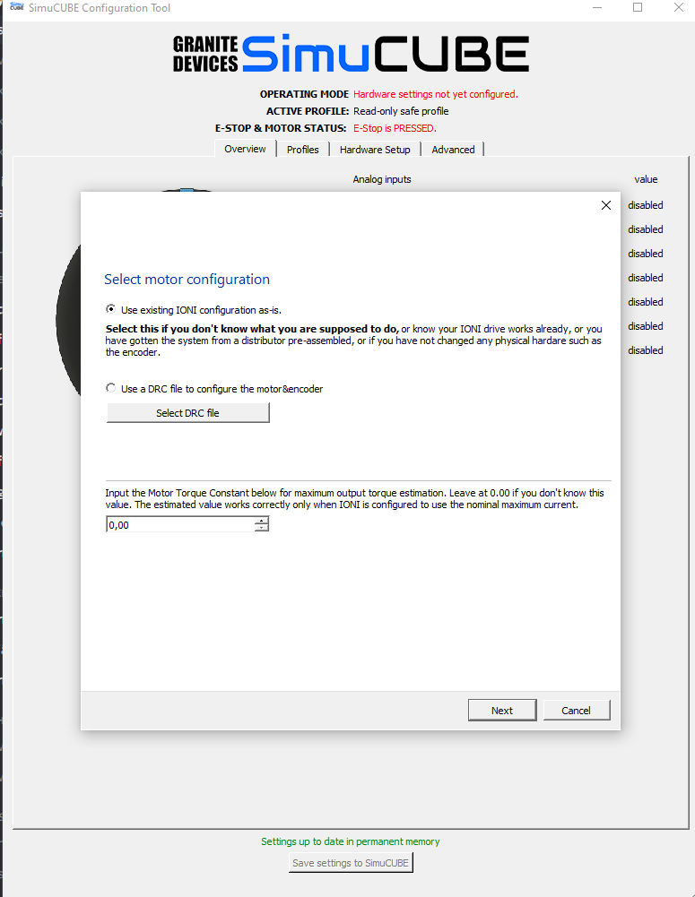
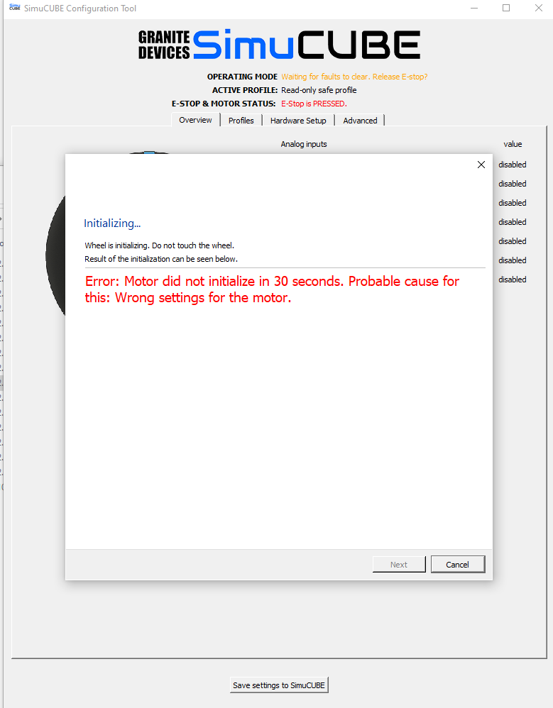
It will probably phase, if you load proper motor configuration and adjust the FUV and FOV settings for 24 V supply. Also you’ll need to put much less aggressive MMC and MCC settings, try with 5 A and 4 A there.
Thanks but i will continue with 48V when it arrives unless i dont have anything else to tinker next week. Probably what is again good for anyone to mention that like example in Iracing forums there is good topic of different motor&encoder drivers SimuCUBE Firmware Settings and Information Thread | iRacing.com Member Forum
I can clearly see now that Youtube videos what i have been looking about installing are not very good as they are missing some steps.
Typically safety critical systems work so, that if a wire is cut / disconnected, the system goes into safe state. Simucube’s STO signal is wired in that way; the pins on Simucube are to be connected only when the button is not pressed in.
Bad explanation from my side. I have E-Stop wired to Simucube and connection in E-stop is so that when button is up circuit is open and when button is down circuit is closed.
But is it actually opposite that circuit needs to be closed in normal state when simucube is operated?
Think of it this way.
If you have an emergency you want to be able to reach over and push the estop in very quickly to disable the drive portion of your control.
If you have it wired to be a closed circuit when the button is pushed in, on emergency you have to reach over and twist the button and let it pop out to disable the drive circuit.
Not as easy correct?
Yeah i understand and i agree that hitting button down you should stop actity
I just understood functionality in Simucube board wrong way thinking it is normally required open circuit. I changed wiring in button to other side of switch so now when E-stop button is up circuit is closed.
When i think of it, it makes sense. Kind of dead man switch or whatever is that term when talking of old trains.
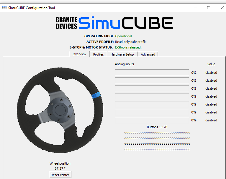
New NDR-480 PSU installed and Simucube drc file for 10010 and BISS C 22 bit encoder installed. Wheel rotations are also recognised. I now need to study again to check what to do nex then.
Oh my! I did firmware updates and set profile what was recommended and drove some laps in Sebring in Iracing.
I can just say that how much wrong i was when i was thinking that there wont be so big difference in FFB when moving from Thrustmaster. There is difference. Big.


 ?
?