I was told they were shipping today, Yesterday was a Canadian Holiday…
Thank you very much for clarifying that.
So I can see a benefit in improving reconstruction filter and velocity/acceleration calculation. It would be two areas I would focus:
- Prediction of torque change from position change for torque interpolation with automatic adaptation to incoming data (I think that this algorithm should not have settings and should just try to do best work).
- Prediction of acceleration change from torque -> acceleration -> velocity -> position. And as a side effect availability of much better data for acceleration/velocity for filters and torque interpolation.
I think I can make some test app in C# that would set up effects, parameters and will allow defining test loops.
It would be great if Simucube would be able to go into the mode in which it will be returning on additional axises Calculated Torque, Position, Velocity, Acceleration and other internal data at high speed. This way I can do running charts to analyze how reconstruction filter works with simulated data, how it responds to the inputs. I would make this app open source on github to get some help since my time is limited.
Btw, one outcome is that it looks reasonable to decrease 900 degree bumpstops to real low value in order to get higher real resolution.
1 Like
From My experience with the SinCOS what you are feeling is what I have found.
Better Filter implementation, haven’t actually ever had a noise issue with my Unit so I can’t comment there… But the filtering improvement is pretty large… As far as positioning improvement it probably depends on how you drive but if you were to just take the Maximum steps that Direct Input allows of 65K+ a little then the SinCOS should at least give you that bump up in resolution from 40K to 65K and with that should come better positioning which May Or may not come through in noticeable ways… It could come through in better feel or slide catching ability or it could come through in minor ways such as tire wear… but yea that is a hard one to determine for sure… I feel that I can catch slides a tiny bit better with the SinCOS or that I can modulate them a little better (i.e. drift the skippy in iRacing all the way through a corner, Not Fast but fun) where I wasn’t quite as able to do that before BUT that being said it could be due to the better filtering and Damping allowing me to better position the wheel in the first place through feel…
As for what SinCOS I am using I have a 5000line Heidenhain on my Large Mige, though I have also used the a 3600 line and 1024 line Heidenhain… I have not used the Newer Mige offered 2048 line unit…
1 Like
DirectInput is 65K for 900 degree. So 40K cpr is going to lose only if you go down to 450 bumpstop distance (that would make it 52.5K). I don’t think anyone goes below 450deg.
Can you run your Heidenhain with a test sequence I suggested above and post how velocity and position looks like?
I will have to go back and search over this thread to find the exact test sequence you used… If you can Message me what you would like direct I will do it as soon as I can… I haven’t really used many of the Granity Testing tools other than to figure out how much voltage was being backdrawn into my system when my Braking resistor ate itself (early SimuCUBE release).
If you can send me the procedure IM that would be great otherwise I will go back through this thread and find it (just will take me longer…
Go to Granity Testing tab.
TSP1 set to smallest value you can feel. For me it was 50 = 0.04A.
TSP2 = -TSP1
TSD1, TSD2 = 0.02
TSR = 20000
Capture signals selection: Position Achieved, Velocity Achieved
Continuously repeating capture = ON
Click Start Capture button
Click TSE = ON
Don’t hold a wheel. If you don’t see at the right side chart proper wave - increase TSP1 and TSP2. If you can see wheel moving by your eyes - decrease them. If you can’t feel it by your hands - increase them. So the purpose is to find smallest movements you can feel.
After that click “save to file” button above the chart and post file here.
Thanks.
OK I have saved that in a text file so the next time I get on it to test I can run this and I will post the results…
2 Likes
1180 is the max for AC the Lamborghini Miura P400 SV is about 1170 degrees .
with that car the sincos will have double the resolution of the 10K at 84K, So the actual DirectInput limit is 72 steps per degree?
With 1170deg you would have 20.2K effective CPR from 40K cpr or SinCos.
And your actual resolution is 56 counts per degree.
With smaller degrees, it’s proportionally more.
1 Like
If thats the case it would be better not to use bumpstops but to set the steering range to the degrees of the car?
At the moment I set the steering range to 1180 and then add bumpstops to stop the wheel from going out of range of the cars steering range.
The bit I dont understand is "with smaller degrees its proportionally more " if the limit is 56 count per degree.
Hi,
I got an update + tracking number in the morning … so let‘s see when it arrives in Germany.
Few things to consider in these encoder studies is that as comparing these encoders that have more than 1M CPR (and are very precise), the test setup is far from ideal for these studies and varies from test setup to test setup. In each test setup the motor is slightly different, different temperature, some of them are slightly more or less used, the motors do not have ideal bearings, some signal noise will come from the bearings to the graphs, some signal noise may come from the wheel/rim if some of the parts are not tightly attached to the wheel and cause slight backlash that may be visible of the graphs and thought to be signal noise. Some people may have something that cause slight vibration to the rig or desk where the motor is mounted or the motor causes vibration to the rig where it is mounted and is visible in the graphs. The motors also have some cogging torque and it is unlikely that all of it can be compensated away so that it does not affect the readings in torque mode. If you think about it, when you have an encoder which has 2M+ CPR resolution, the 1 count precision is 0,00017 degrees (if we forget signal noise). There are rather many factors that can effect to the studies and conclusions of quality of this or that encoder.
1 Like
Just set steering range to the car limits. You get better real resolution this way.
Cool its a bit messy for AC as you would need 2 profiles for each steering range one in SimuCUBE and one in AC. Ive done it in the past and thought the ffb felt better but was told it was placebo. 
That’s true. But I believe that it’s better than nothing - we can see noise levels, oscillations remove much of cogging torque issue, rig vibration also barely important. Take a look at my charts above - it’s clearly visible sine wave which you can’t see on the wheel at all, but if you touch it - you can feel it quite well.
Ideally it’s worth doing experiments by somebody who has time and resources to try encoders, but that’s what we got so far.
Anyway, my expectations that Chinese SinCos is already fine since it’s at the limits of SimuCube resolution.
Btw, SinCos is not very precise at all. It’s detailed and inaccurate. But not precise.
I’ve spent years tuning and fault finding large torque and speed Referenced servo systems, And what Tommi Says it correct you would be surprised what mechanical issues can be diagnosed from voltage and current charts. Each system is different and each person is looking for a different thing the great thing about the Simucube is the varied equipment people use.
Yes, you can see noise or think that that something is signal noise (and not caused by the mechanics of the test setup), but it is a bit doubtful that one can isolate the source and truly pinpoint the source in this sort of test. The motor and its bearings in this test setup + the drive itself are 1 test setup and are far from ideal test setup. We can learn if there is something wrong with the equipment in quite large scale, but to find some small issues of the encoder or to use the data as encoder analysis, for that I have my doubts. So if people do these tests, we may find if there is something wrong with the encoder, for example is the encoder a bad sample from a production batch, but if the production quality is good for all the units, then, in my opinion it is not very likely that we can find a lot by doing these tests.
By the way Mash, if you have the time at some point, could you remove the SinCos from your setup, place the encoder on table and see that does it have drift or less signal noise when it is not mechanically connected to the motor + drive? If it really has drift, it might be something that could be reported to the manufacturer so that they could improve the model. They likely actually listen this sort of information.
Compared to what encoder technology? Where do you get this information? For example this Chinese SinCos encoder model is optical encoder, not magnetic.
I have the same expectation that it is actually very good “bang for the buck” but time will tell will people like it.
OK I have done what @mash asked with my 5000line encoder at full resolution on a Large Mige @25A MMC.
So here it goes a few files here at different levels and I also decided to turn on tracking Error which is interesting in itself on a couple of them.
anyway it is TSP1-2 @ 10, 25, 50, and 200 and 10 and 200 with tracking error:
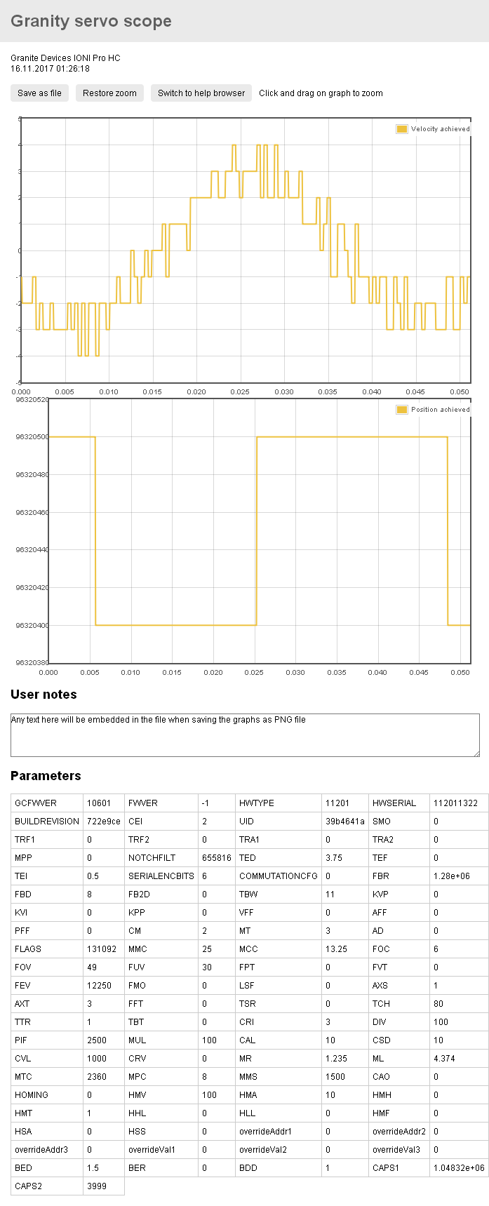
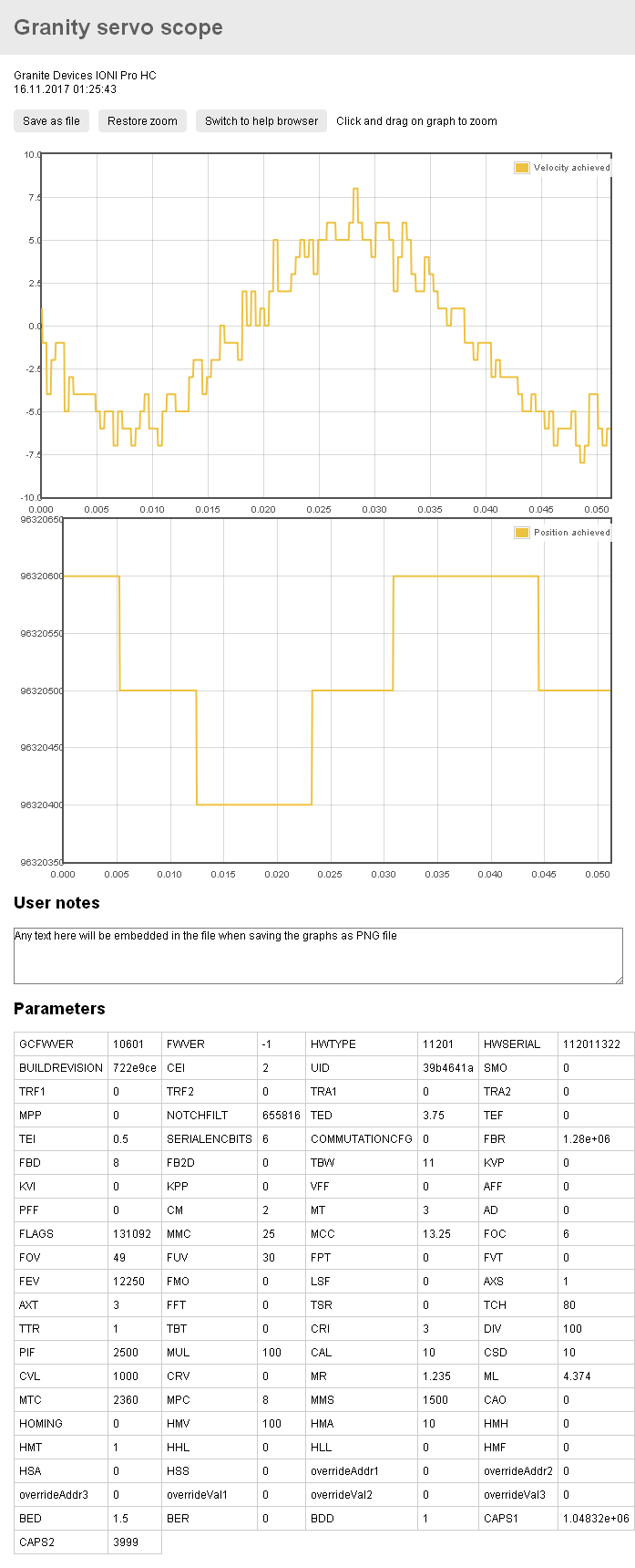
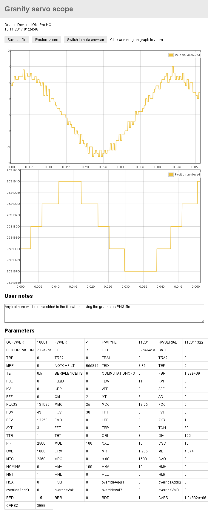
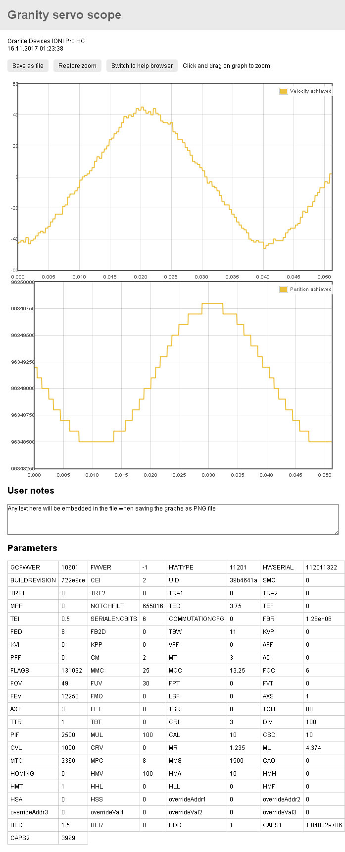
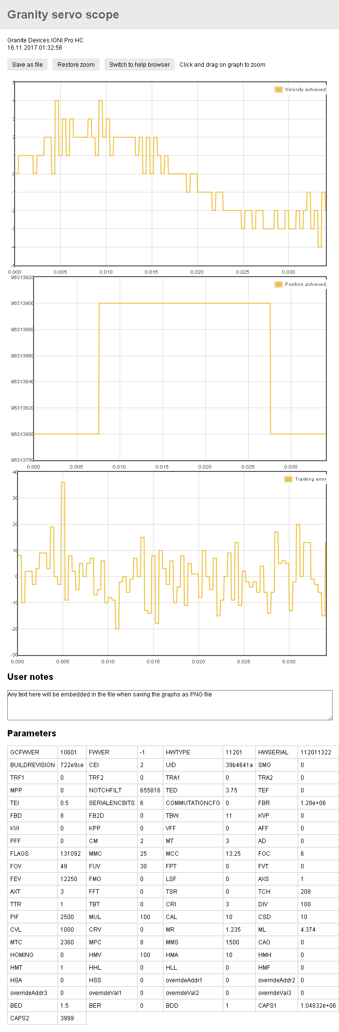
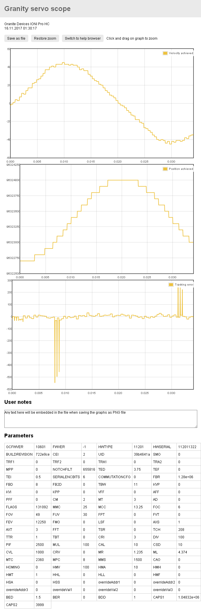
OK well after I did all of this it appears that it is all meaningless in a way… as I started to play with filtering while watching these graphs and that has a huge effect on what would be considered so called noise. The more damping the less “noise you get” but you also get a delay in position change. The less damping the more overshoot you get which leads to some nasty errors in positioning. I found that the settings that I came up with while driving actually do make for a pretty decent speed and torque curve and I also now know what and how the servo motion does when certain filters are used or not… Interesting stuff… But there is actually less accuracy having zero damping, at least according to the graphs, but with that there is also a more responsive less lingering torque curve, so it is a tradeoff…
I agree that drift could be mechanical nature. At the same time I have a feeling that rotor friction and inertia keeps it better than encoder could hold itself. I will try to do test when it’s disconnected. I can as well, probably disconnect power from the motor and check if encoder drifts or not.
What I’m curious is a comparison of hi-frequency noise. We have 2 guys here posted graphs showing same hi-frequency noise. We are on the completely different rigs and see same exact noise pattern of 3 bits with spikes to 5bit. Drift could be some electrical capacity issue. Could be by design of Simucube ports.
But my point is that slow drift, probably, doesn’t matter. Noise is not nice, but then with enough filtering it will be gone for good.
SinCos is not precise compare to enclosed circuits of digital absolute encoders. There are 20, 21 bit per turn encoders that already did all job of filtering and trimming and declared accuracy of them significantly higher. So I can assume they are more precise (means repeatable). And more accurate (means close to the truth). But they probably won’t give more resolution and would cost more (except this Chinese Tamagawa I found, which can’t be used by simucube).