I have a question regarding IONI regarding a SinCos encoder. I have no experience using SinCos encoders so it is possible that I am making some stupid mistake.
My hardware configuration:
-
IONI with IONICUBE.
-
A linear motor with a linear SinCos encoder.
-
Drive firmware version 1.7.21.
-
48V high voltage power supply.
Problems arise when:
I have successfully got the motor to move in the “Digital hall sensors” feedback device mode, but I experience problems whenever I try to use the SinCos encoder. The problems I describe below arise in torque control mode with setpoint 0.
How it behaves:
The first way that I noticed the problem is that the “position feedback” field under the Granity Testing tab tends to drift towards negative values. It almost doesn’t happen when the drive is software disabled (Esc in Granity). The motor has about 120 mm of motion range: If I enable the drive in torque mode with setpoint 0 and manually move the motor over to one side and then back again, the reported end position is very roughly 120 mm (it varies with each try) smaller than before, even though the real position of the motor is back to where it was originally. For obvious reasons, this prevents the system from working.
Because the drift problem is almost entirely gone if the drive is disabled, I figured that it might be an EMI issue (there is some motor hiss). However, I do not think this is the case, because what I see in the Granity scope is that the “position achieved” and “velocity achieved” plots display effectively no noise (never > 1 least significant bit), except that the position sometimes jumps by exactly one encoder line (20 μm). The jumps happen more when the drive is enabled, and when the drive is enabled, there are more jumps in the negative than in the positive direction. The jumps happen when the motor is moved (but happens also with tiny movements), usually not when it stands still (but sometimes it ends up in a state where it keeps drifting constantly when standing still).
-
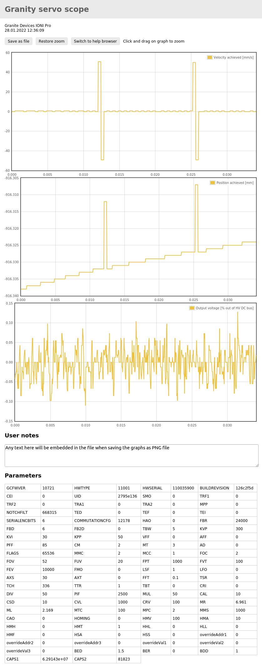
graphs_3.png shows a couple of these jumps, and shows that the jump size is 20 μm with otherwise no encoder noise (other than quantization noise). For this capture I moved the motor slowly in one direction. I believe the drive was disabled for this one, and it characteristically for the drive being disabled jumps back to the right position here.
-
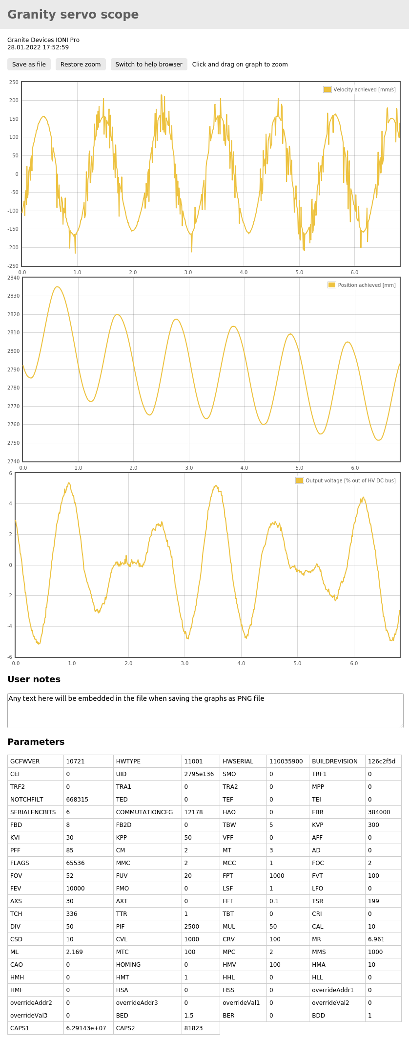
graphs_5.png shows a lower sample rate capture when I moved the motor back and forth by a couple of cm or so, with the drive enabled (torque setpoint 0). You can see the sinusoidal motion, with the erroneous jumps showing up in the velocity graph as random fixed magnitude peaks, and in the position graph as a negative drift.
I cannot think of a way that the SinCos encoder line could be connected incorrectly, or how they could be noisy or otherwise wrong in a way that could cause this particular result in the Granity scope. An instant jump of an integer multiple of the encoder line length should show up electronically on the SinCos data lines as nothing at all, no?
Could this be an issue with the encoder’s index line? The problem occurs along the entire length of the motor’s range of motion though.
How I would expect it to behave:
I expect the behavior to be the same as it is now but without seemingly random sudden 20 μm jumps.
I have attached following files:
-
Granity scope screenshots, see description above.
-
Granity .drc configuration file.
Thankful for any help,
Perlinear_sincos.drc (8.8 KB)