I have just recently found out about & got my hands on Ioni, as well as Ionicube.
I thought it could be useful, to try and put together an A&O topic, for some details on getting to know the Ioni and Ionicube products, from unpacking to “testdrive”, and add up to this topic appendingly. Also bring up a few questions to publicity, that i have been wondering about myself in a beginning phase.
So, im almost done wiring up, still need to solder a D-Sub connector for the encoder of my motor etc.
Im curious to try to get to know the basics of usage by simply wiring up one motor, and using a single axis first.
So…
Do i mount all the drivers on to the Ionicube for this as well, or should i mount only a single driver? If i remember correct from smaller projects and components, a Driver doesnt like to be around, without a motor connected to it. “Atleast if it is energized”
I noted the manual stated, it is very important to check that the Condensators are fully discharged when mounting the drivers to the Cube. So this is something i will have to keep in mind and remember later on, if adding more drivers. “Note To Self”
And once one masters the art of using it, and tweaking it : )
Just got the encoder cable soldered, still need to double check it.
Have not got to the part in the manual yet, where communication with the board is presented, just out of curiosity. Does communication on the Rj-45 port work out of the box ? Because then i think i would skip USB from the beginning.
Hi Mate,
You cannot directly connect anything else to the ‘RJ-45’ port, than through a USB/RS485 converter! B very careful with that comms-port, any mistakes there and it will pop the comms-line.
Please check the wiki carefully, there are also other signals on that line that needs connection. There is a small break-out board available from Granite Devices for that purpose, otherwise you can hack a Norma straight-through Cat5 pigtail…
Running the motor without Regen is not advised though, as even spinning it up and slowing it down will create feedback on the uvw lines…maybe Esa can chime in here…
In most installations braking resistor is not needed at all. Resistor is needed in cases where fast moving motor with high inertial load is stopped rapidly causing conversion of the kinetic energy into electric current which needs to be dissipated by a resistor. Experimenting without resistor is safe as drive’s overvoltage protection will prevent any damage occurring. If drive faults to overvoltage fault during deceleration, then try adjusting Over voltage fault thresholdFOV to higher value or add a braking resistor.
So… Question is rather, Ive made the Encoder Cable, Mounted a single Ioni, Wired a motor, that is mounted without any load to a board i made and fastened securely, Connected the 24v logic power, Can i proceed without the resistor?
Got a Power Supply waiting for use on HV as well.
There is no need for me to even spin the motor a full revolution at this time.
You can test/setup an IONI without a motor connected. It will search for one, but if not found, you’ll get an error flag. No harm will come from this whatsoever.
In IONICUBE 4X, you will find a USB connector. It’s practically identical to the SMV2USB adapter, so you don’t have to use RJ45 cable. It’s also possible to connect multiple devices via the RH45 connector, and use just the usb cable for pc connection. In multiple device configuration, the last and only the last device needs to activate RS485 termination.
The regenerative resistor is to protect the drive power stage transistors from over voltage condition. If you are testing a setup with a lower HV voltage, say up to 24 V, then you don’t necessarily need a regenerative resistor. Also if you are driving the motor with low speeds and accelerations, then you might not need the resistor. If you are certain that in no situation the HV voltage rises higher than 60V, you should be safe without the resistor.
Allright, So now i got to the point where i start setting things up in Granity.
The fault indications on the Led´s started dissapearing one after another.
However, Now i am stuck with a SSSL …- On Led number 2.
Other/unknown, possibly configuration error such as motor mode Motor typeMT not selected
I have selected Stepping motor and added the Motor details.
I set the Max speed to a value i assumed "failsafer" for running withouht Regen Resistor: 5 rpm.

MCC to 0,6 A

MMC to 2 A

MR to 0,33 Ohms

ML to 3mH


Quadrature Encoder 1 with 1000 PPR in the box as well.  ```

Any ideas?
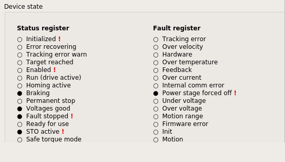
The red exclamation marks show the status fields that are a cause for fault or other concern.
In the screenshot, it can be seen that the e-stop is activated, so the drive is in a fault stopped stage, it has not initialized at all since last start, and that the power state is forced off.


 ?
?