My hardware configuration:
-(ioni 4x)
-(mige 80st 4/12nm 220v)
Problems arise when:
-(describe how/where it happens)
i have work with argon and simucube and now i buy a ioni 4x, dont start with his yet i want to know about the performace what RPM i can get,i will have, if my motor is 220v 3000rpm, and i will use a 48v power suply, i will have what voltage to calculate my rpm?
i fount it on wiki
I.e. at 48V supply, the maximum three-phase motor output voltage is 32.2 V RMS phase-to-phase
it will be 96,6V with my 3phase motor ? 96/220 X 3000 RPM = 1317 rpm??
i start the project with that RPM i will incresse speed with high ball screw,
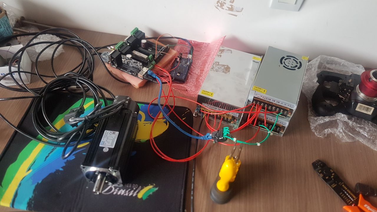
the photo
the motor is working without error in granity
im using the same code to my stepper, EN, PULL and Direction, i put the pin(adruinos) 5(en) 6(pul) 7(dir) on X4 - 1(en) 2(pul) 3 (dir) its right? because the motor dont moves, have sugestion?
You can check the read setpoint pulses with Granity/Testing using the servoscope. Select position setpoint and position achieved and you can see how the motor reponds to the steps from the Arduino.
Thz esa its works, my mistake was see 1,2,3 but is 1 3 5, i checj wiring of beano is ioni 4x project for open sim wheel and now its working and i can get 8-8.25 rps/s is about 500rpm, more than we calculate, with 9-10 rps i get error and drive stops, lets see when i put load wheigh if 8rps will dont fault, thak u very much.
I more thing, i using a 80stm04025 4/12nm how can i how the max mmc (amps) i can use to obtain 4 or 12 peak nm? I now my mige 130st (small mige sinulaters call) is 12.86A to get 20nm (peak) in this motor
Very thz is working very good and rpm in testing is max 9.5rps now, and i will get 9.5 x 25mm ball screw 237mm/s thats is very good.
My project is a linear actuador, and when the drive stars, the motor turns right and left, and my actuador can be in the finish line and the motor cant do this moviment in starts in 2 directions, just one, can i modify ou remove this movement when starts?
Is there enough space for the initialization in the middle of the actuator? If the motor hits the end while phasing, the magnetic angle information is not correct and is highly likely to cause issues in the motion control. These include stalled motor, much higher drive current, or runaway motor.
I even have the margin for the engine to start in the middle of the actuator, the problem that the actuator due to the weight of the cockpit always throws the actuator to the lowest level until it turn off, I still have not mounted the actuator on the servo, thinking to verify the initialization and by a thread that the sense of initialization if it is standard, do not hit the end of course, but i thing the motor turns more.in one direction, but will hit the end, follows video attachment of my project with step motor ita working, the settper dont moves when starst.
Im using a simucube with 130st servo motor for sterring wheel and 3 stepper for motion, stepper does a sound when moves, because this i want use servo, that dont do sound on highs rpm like stepper, sorry my english
I try select hall sensor and its working… without starts phase turns, i dont know if my servo have hall sensor, i think no, is a encoder 2500ppr but is working… with position mode