FFB cut-out in Assetto Corsa

Hey guys, i am running the really old VSD-E and small Mige motor for 3 years now, it has to be the first ever iteration of OSW wheel, with the disco board, VSD-E and seperate power supply.
It has served me great for a long time. (and still does)

I am mostly racing in Assetto Crosa but also do iRacing and RF2.

There is some issue that appears randomly that i have been trying to get to the bottom of, maybe you can help me.

When i am running low filter setting in MMoS, say 2 or lower, the FFB of the wheel sometimes randomly stops responding while driving.
I have to pull the plug on the control box and then its working again.

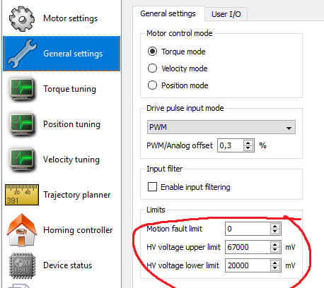
By the way, my TBW setting is set at 680.

To replicate this, i need to be running some damper (in MMoS or a minimum value in gyro, lets say 0.15), filter lower than 2 in MMoS and it happens when i do this: Lesmo2 at Monza, going sideways and i have to counter steer while on the curbs (very quick change of direction on the wheel (opposite force to the car’s self centering forces) then my wheel dies. It turns left and right but the ffb is dead.
I can fix this by running filter at or or higher but i am losing some details.
This can also happen in other tracks with similar scenario, counter-steering while on the rumble strips, its just that monza can make it appear very quickly.

When checking my VSDE after this happens, i get some LED blinking that when checking the troubleshooting of the granite pdf it says : “HV bus over voltage or under voltage fault” (blue and red led blinking).

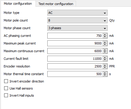
I tried lowering the amperage from 11 to 8 in the VSDE configuration just to be safe and make sure it wasn’t my power supply’s fault (not being able to put out the required juice), but i am still getting it.

Any ideas what might cause it? I thought the power supply wasn’t enough but even running it at really safe values i still get the same issue.
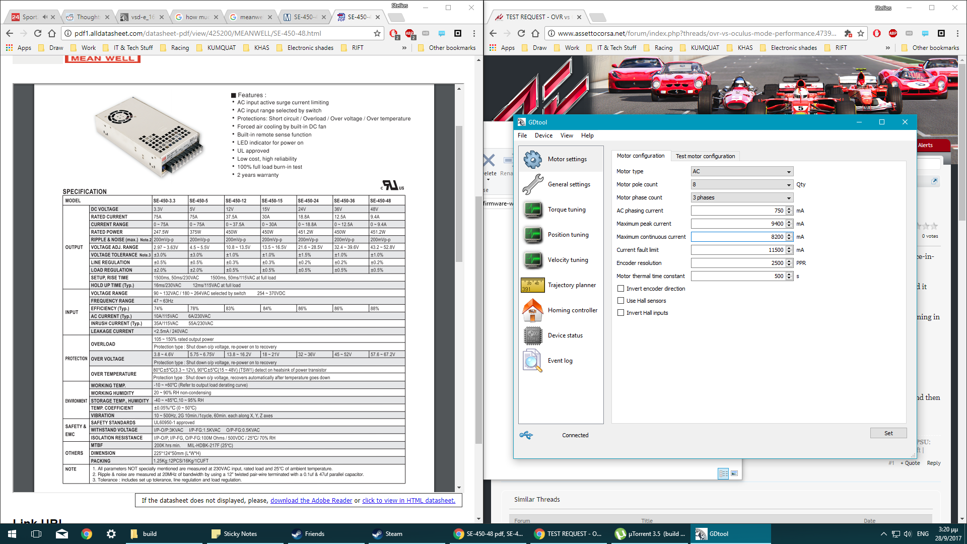
My power supply is the Meanwell SE-450-48
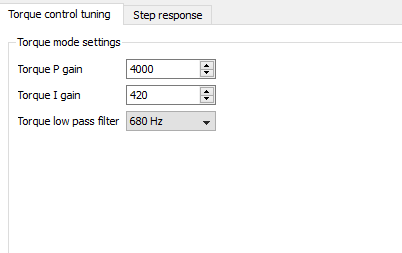
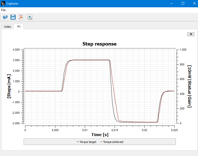
Here are my settings:

Any help / ideas would be greatly appreciated!

Hmm I wonder if your power supply may have given up the ghost a bit and is not outputting what it should under load… This is similar response to what happens when the newer units run out of wattage. but 450 should be more than enough for a Small Mige.

Does the OLD GD Tool have fault parameter settings?

Hi Stelios

What are your settings for the voltage fault limits? This sounds like the motor is generating voltage that reaches higher than the over voltage setting.

VSD has 200V rated power stage FETs so you can increase quite freely the over voltage setting to prevent over voltage faults.

Do you have regenerative resistor in use?

Kind regards,
Esa

Hello and thanks for replying,
Do you mean this?:
2

If not, check my OP, i use my power supply’s maximum output as “current fault limit”
Those are the settings i currently use, while trying to troubleshoot.

Hello, if i understand correctly you are asking me the same thing as bsohn, i hope my screengrab helps you.
Yes, i am using a 10ohm brake resistor that is working correctly, checked it 2 days ago.

Hi Stelios

A couple of things you can try out. Try one at a time so that you’ll know what was the bottleneck.

One is to increase the HV upper limit. You can practically set it to maximum (~170V if I remember correctly).

Decrease the lower limit.

Turn off the system and wait for the HV voltage to come to zero. Then move the VSD power connector many times back and forth. The contact might get worse by time, and moving the connector might increase the quality. You can also remove the connector completely and sand it very lightly.

Kind regards,
Esa

Thanks for the recommendations.
I decided to test all 3 of your recommendations together and then start undoing them one by one to find whichone is causing the issue.
The reason i did this is, i am banging my head against the wall for the past 6 months and i just want to make sure i fix this asap.

Sure enough, after about 2 hours of testing i did not get the dead FFB problem, but sometimes this issue was hard to reproduce.
Good news then.

I promise to start undoing the changes and get to the bottom of this and i will report back.

One last question, are you sure we are not going to do any damage to the internals by using so high hv voltage upper limit? (i use 150v now).

Also, after looking at my picture in the original post, what values do you recommend for the peak current, continuous current and the current fault limit - according to my power supply?
I want to run the motor at 90% of its capability, but not put a lot of strain to the vsde and power supply.
Thank you.

So, after i did some racing today, i never got the FFB is dead issue, but what is new is that in 2 hours my steering wheel died (ffb AND directions-i couldnt turn) for half a second and then came back again.
Half a second is enough to make you meet your maker in a sim of course so it is really annoying… any ideas? :confused: @Esa

To give you an idea of the duration of the steering fail, check this video at 46:38.

Hi Stelios

The function of the regenerative resistor is to make sure that the operating voltage (motor side) doesn’t rise too high to break anything. Mostly the power stage or the PSU. VSD power FETs can handle 200 V, so if you are not turning the wheel very fast, the HV voltage shouldn’t reach that high in any situation. Also, if you still have the regenerative resistor wired, it will make sure, that the voltage will be under limits.

Depending on the PSU, the generated voltage might cause some issues, this is at least for switching power supplies. Linear PSU’s are likely to have large capacitor banks, and their electronics are such that there should be no chances of anything breaking (transformer -> bridge rectifier -> capacitors).

Most switching PSU’s are isolated, and they have optical feedback to the switching controller. These circuits usually work so, that when the set output voltage is reached, the switching is stopped, or it’s frequency goes slower to prevent voltage rise. However, depending on the PSU, there might be over voltage protection or other circuitry that would react to the generated voltage. This over voltage protection could halt the PSU for a short period of time or cause other .

In case of over voltage protection dropping the output voltage, the VSD would give the undervotlage error fault.

If you want to rule out the chances of PSU reacting to the generated voltage, you can put a 10A rated diode after the PSU output voltage. In the case of the generated voltage rising, the diode will block current from flowing into the PSU, and the VSD regenerative circuitry would take care of the excess voltage if needed.

Also, the wheel position is based on the encoder signal. If this stops for awhile, then I’d check if anything abnormal is happening on the logic side. That kind of short brake could mean, that the processor reboots for some reason.

Still, assuming that the encoder signal is wired directly to both the VSD and the STM discovery, the state of the VSD processor shouldn’t have much to do with the Mmos getting the encoder pulses. This in turn could mean, that the encoder doesn’t get the 5V voltage for some reason, which in turn points to the logic voltage of the VSD.

I’m not sure if I answered to your questions exactly, but here’s some thoughts anyway :).

Kind regards,
Esa

Esa, thank you for your reply (many years later).
I never managed to get to the bottom of this, and after moving houses a couple of times i decided to set this up again.
There is still an issue, albeit a bit different.
While driving, the wheel just stops responding and keeps going either left or right until it hits its stops from the MMos utility.

The VSD-E LED’s are not showing anything abnormal, the disco controller led look normal too.
I dont hear any windows usb disconnection sounds, so its not a usb issue (my pc is also different than 7 years ago…)

I was hoping there would be someone with a similar issue around here :slight_smile:

Hi Stelios

You might want to check with GDtool that the VSD responds for setpoint commands normally. I.e. turning to left/right with the correct response.

I’d remember that the OSW outputs PWM signal with 50% pulse ratio being the zero setpoint. From this, if your motor turns continuously to either direction it would be because of the PWM signal being either 0% or 100%. This however would likely to be very fast rotation depending on your PSU voltage. With 48W Mige would not turn very fast.

Please check your wiring that there are no loose contacts.

Regarding the original HV voltage issue. I remembered that the green HV connector on VSD boards might age so that they loose contact every now and then. My old cnc-machine had this issue, and I sanded the contacts if I remember correctly after which the HV voltage issue was fixed. Contact spray or soldering the PSU wires directly (or adding an in-line connector) to the pin is also a viable option.

Kind regards, Esa

Thank you for your help.
I have something kind of funny to share: after reading your comments, I moved the control box on to a different desk than the rig, so I can isolate the vibrations coming from the wheel, and what do you know, I completed 2 online races today without issues.
I don’t want to jinx it, but it seems that something is loose in there.
All cables (almost) are soldered, and i cannot spot any issues, it could be some solder on the VSDE pcb itself maybe? (not its pins).

I made this OSW using the small Mige, 130ST-M10010, VSD-E , the STM disco board and a Meanwell 48V 450W power supply.
Since the simracingfr forums are down, i cannot find anyone with a similar combo, so i was wondering if my GDTool settings are ok, especially the power to the motor.
I would like to run the power supply at about 80%, so I am attaching screenshots of my GDTool settings in case someone can comment on them.
image

While i am at it, here are the rest of the settings, i think i could optimize my Torque control settings because the FFB is a little muted / filtered (lost a little detail), but it has been 5-6 years since i last tuned it and i can not find my .drc file.
I don’t remember which settings give more detail etc, any advice much appreciated :slight_smile:
image

Hi Stelios

Settings and the torque step response looks good.

It is possible that there is a cold solder or something that kicks in during vibration that causes the issue even though the VSD has been properly soldered.

Kind regards, Esa

Thank you for your help, i will do a very good inspection of the pcb’s in the following days and i will update.