Connection button, accelerator, brake on simucube

Hi. I have a simucube that I bought 10 days ago.
I want to connect buttons to raise and lower gears, or for other options.
I want to connect potentiometers for accelerator, front brake, rear brake.

I have seen this page:
Http://granitedevices.com/wiki/SimuCUBE_connector_pinouts

Http://granitedevices.com/wiki/SimuCUBE_wiring_overview

Viewing this page as I do not know much about electronica, I do not know how to connect them.
I would like someone to tell me graphically how they would connect. And as it is configured in simucube software.

A greeting.

Hello,

This picture shows very well how to connect buttons and analog inputs:

Option 1: Basically, you just need to cut a leftover straight (not cross-wired) network cable with RJ45 connector on one end. You will need to use a multimeter to verify which connections / wires are correct.
Option 2: Use a RJ45 terminal block, such as one like this:
http://www.ebay.com/itm/Ethernet-RJ45-Female-To-Screw-Terminal-8-Pin-CCTV-Digital-DVR-Adapter-Connector-/391724179456?hash=item5b3494a000:g:71gAAOSw32lYwPow

In the popular 3rd party software (MMOS), you will just need to enable analog axises in the setup menu.

In our soon upcoming own firmware and configuration tool, there will be much better UI for management of the analog inputs.

1 Like

Thanks for the quick reply.
I do not understand electronics and I do not see the connection X11, brake, accelerator.

Can you draw me what the potentiometer connection would

look like?

1 Like

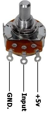
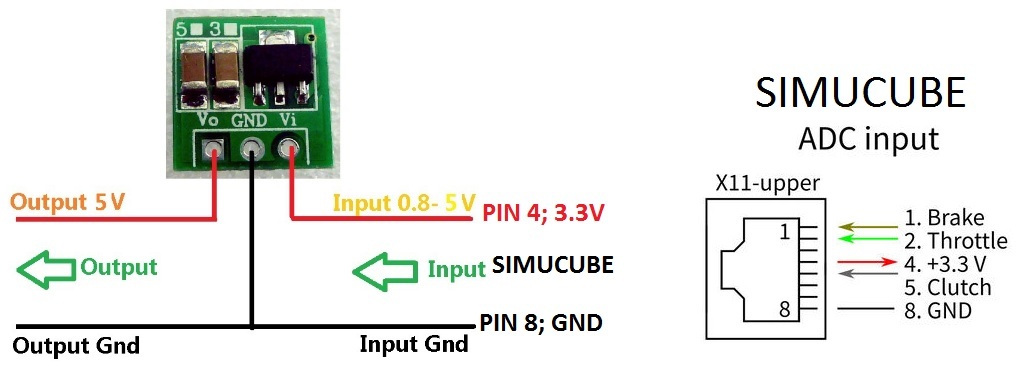
Elecrically, a potentiometer looks like this (note that SimuCUBE uses 3.3V, but this can be ignored if you just follow the wiring example and connect to the 3.3V pin).

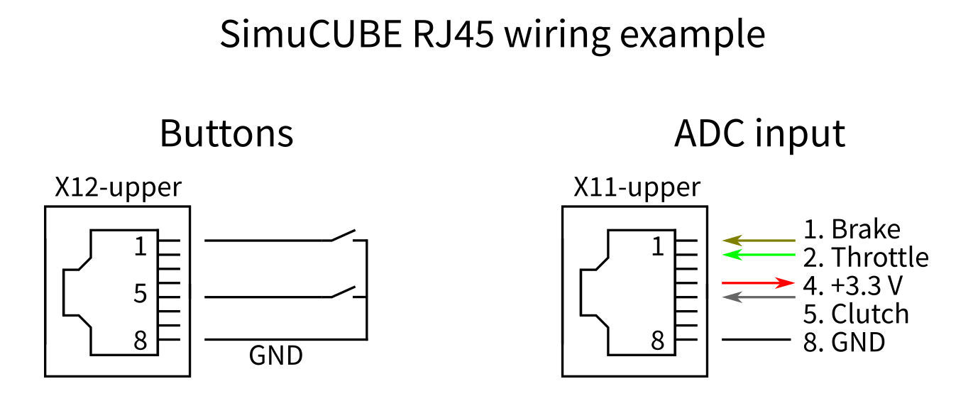
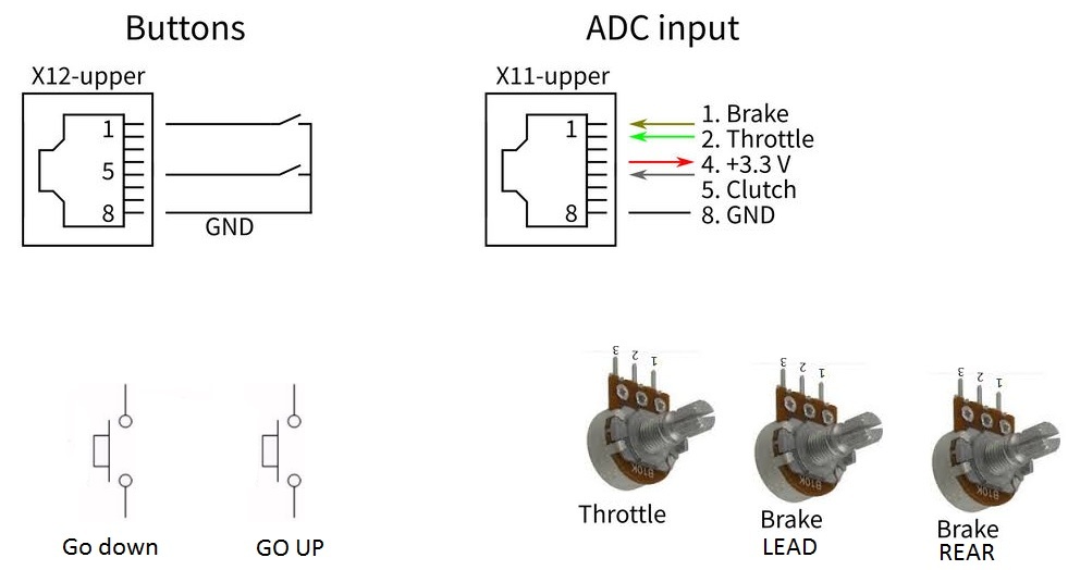
and a button can be wired between the X12 pin 8 and any other pin on X12.

See also http://www.wikihow.com/Wire-a-Potentiometer

1 Like

Thank you, everything much clearer now.

I’ll make the connection to see if it works for me.

This input converter can be used 3V output 5V.
From the 3.3V output of simucube is connected to the input of the converter so you have 5V

You can connect potentiometers directly, they don’t require a specific operating voltage.

Do not connect any external 5V voltage to the X11/X12 connectors, that will damage the SimuCUBE.

1 Like

Coming to think of it, using this kind of step up voltage converter, will make the potentiometer output 0 V to 5 V, and that 5 V will damage SimuCUBE.

DO NOT USE this kind of voltage converter. Potentiometer (variable resistor) can be connected directly.

OK, I will not connect anything to 5V
But in the top drawing of the potentiometer I put GND, Imput, + 5V.

I do not understand why you do not output to 5V. Other plates like leo bodnar, arduino … take that tension.

I want to connect a 60psi pressure sensor for the simulator: http://www.ebay.es/itm/Pressure-Transducer-or-Sensor-Stainless-Steel-For-Oil-Fuel-Diesel-Gas-Air-Water-/ 401197952072? Var = & hash = item5d6942ec48: m: mlub-Yg-PipJXV3nIVKj6gA

Do you think I can use this sensor with 3.3V?
How can I use it?
So for the accelerator I am going to use a potentiometer I will not have problems when connecting it with 3.3V. Will it work just like if I use another type of electronic board?

Arduino’s and Bodnar circuits use 5 V microcontroller, where as the STM32F407 on SimuCUBE operates at 3.3 V. That is the main reason.

You can try to use that sensor you linked. Most of these sensors work correctly with slightly lower operating voltage.

I have pedals including pressure transducer for brakes working nicely through SimuCube.

I am using a 0 to 1000psi 5V transducer and 10k (I think) potentiometers with no problems.
Transducer connected just like a Potentiometer.

60psi is fairly low pressure for a brake pedal.

Hi.
I connected the keypad in X11 simucube and potentiometers in X12
I have tried window 7 setup gaming devices and it works fine.

I’ve continued with steps 2, 3, 4 … https://granitedevices.com/wiki/Installing_MMos_firmware_into_SimuCUBE
At the end of all the steps I have connected and the keypad does not work.

What can be?

The PC detects the command but does nothing.

a greeting

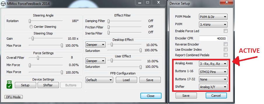
Please see the connector pinouts. Buttons should be connected to X12 and potentiometers to X11 upper connector if you want them to work with MMOS firmware.

Did you manage to install MMOS firmware? We don’t offer official support for using it.

Hello.

According to the official website X12 upper is for buttons and X11 upper is potentiometers, according to official website.

Https://granitedevices.com/wiki/SimuCUBE_connector_pinouts.

I installed the MMos firmware according to the official page, following these steps:

Https://granitedevices.com/wiki/Installing_MMos_firmware_into_SimuCUBE

The PC detects the controls and before doing all the steps that the web says, it worked well.

What steps do you advise me to do?

Thank you.

is it a matrix-ed keypad like most of the are. If it is wont work its just for normal momentary buttons.

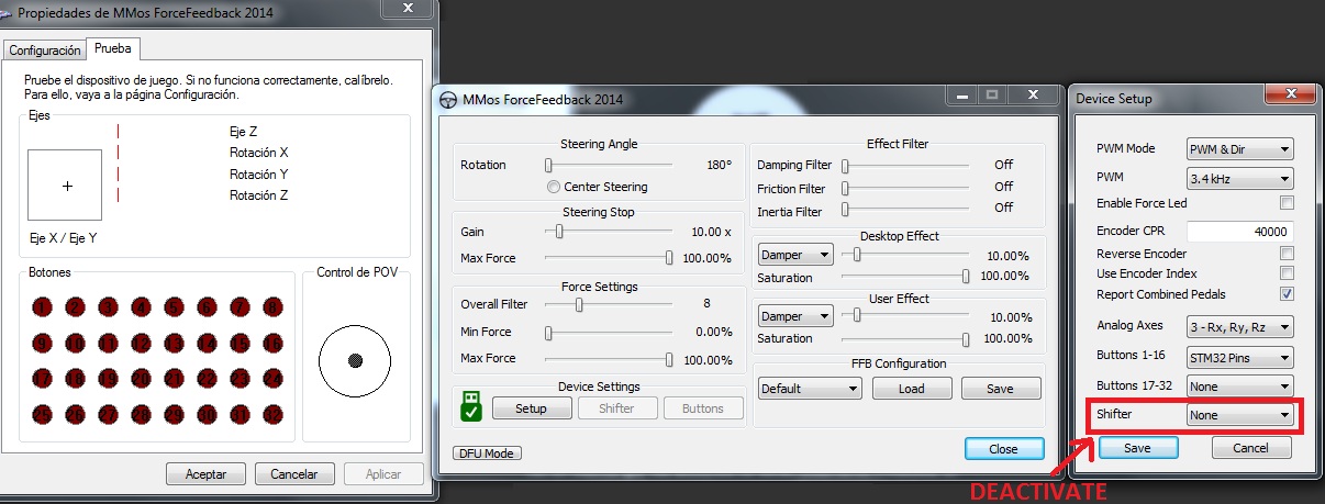
How is it possible that at first they worked and then no longer work?
The PC if it detects the plate but the buttons and potentiometers do not work, it does nothing.

Got it, I did not have the signals I marked in red activated.
Thank you very much for your patience. It works perfect.

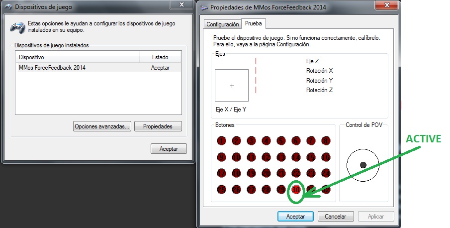
I only have one problem, without touching buttons, without touching potentiometers, without touching anything.
The number 30 is in red as active or pulsed.
Because it can be?

A greeting.

I’ve always had issues with buttons on mmos fw. Same issue as you, either 30 or 16 will stay on, depending if I used direct connection or SPI buttons.

Cheers,
Beano

To remove the number 30 activated, Shifter must be set to None.

It looks like the number 30 is no longer active.