Hi, so I have connected the G27 pedals to the dedicated X11 upper via a serial breakout connector and cutting the CAT5 cable in half, works fine.
Now can I connect the shifter in the same way to a different RJ45 port as they are for buttons and encoders right?
Would I be able to keep all the buttons? Because I noticed ports are 7 pin plus 8th for ground. Not opened the shifter but does it have it’s own small board inside to contain everything to one serial connector?
If not any other way I could possibly connect the shifter to the board directly so I don’t have to go with something like bodnar usb adapter because I already have 2 many usbs connected, would like to keep it on the board if possible.
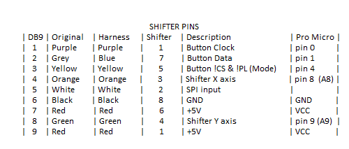
Would this even be possible because looking at serial pinouts coming from the shifter it has 2 5v inputs. Not 100% sure how accurate this is just from what I can find on the internet.
Would it be possible to rig it up somehow with the internal pinouts?
Now that I think of it, it might be that the X and Y axis of the shifter are parsed as buttons on the G27 wheel base based on the positions reported and that there is a calibration app for this for the Bodnar adapter.
Simucube firmware does not have this type of logic implemented. However, we are always open to integrating the logic to Simucube firmware if there is an implementation for the STM32F4 platform somewhere.
“Now that I think of it, it might be that the X and Y axis of the shifter are parsed as buttons on the G27 wheel base based on the positions reported and that there is a calibration app for this for the Bodnar adapter.”
Yeah I have a feeling that might be the case, if that is something that you guys could possibly look into would be great. Of course provided that it can work with the current revision of the board design and existing connectors. I guess it would be possible to grab 2 5v inputs from somewhere else.
Not sure I’m understanding the picture correctly, What’s pinout 2? For that green block? X7? Well looking at it again I guess so… But it would not be able to work through that tho wouldn’t it? Sorry I’m dumb. Serial needs 8 pins I think at least from one config I have seen but also seen one using all 9. I can open up my shifter and actually see how many are going out.
Pinout 2 is the green block where the “2: Fan power & ext. potentiometers connector” arrow points to. There are three additional non-ESD protected analog inputs in that port. Those inputs are not 5 V tolerant, if I remember correctly.
Simucube 1 has reached EOL, so there is not active development for it, and there are no replacement DIY boards planned due to market being moved on from DIY boards in the recent years.
Doesn‘t this have a 9 pin sub-d connector per default?
Should be the same as the G25 had and there for you can use an Arduino or compatible board to connect it to the PC as it is using a simple MCP3208 for the 2 axis and an spa interface for the buttons… there is a code available that even allows to switch to an analog handbrake mode …(no break in the center, full at bottom position, of course with no resistance without modding the hardware) by pressing the left or right three red buttons together. Search for "g25 shifter teensy"and you see a link to isrtv with all the information needed.
I used this for several years as I anyway needed to program a controller replacement for my old pedals that didn‘t work wirh windows 10.
X and Y are defining the left/right and front/back position of the stick, so there is a certain combination of these two values for each of the gears - or in simple words … the shifter is an analog joystick with guides.