I wouldn’t actually go from a small to large bit unless you’re using a drill press or mill. Just start the hole will a center drill and use the full size you want. Otherwise you won’t be effectively using the full cutting edges of the drill bit and 9 times out of 10, it’ll dig into the material more than it can handle and cause issues. That is unless you have super human control over a hand drill or you have a tool grinder and can regrind the tip to have a more shallow angle, but I’m assuming the poster would get the typical drill bits for metal that are at the average hardware store.
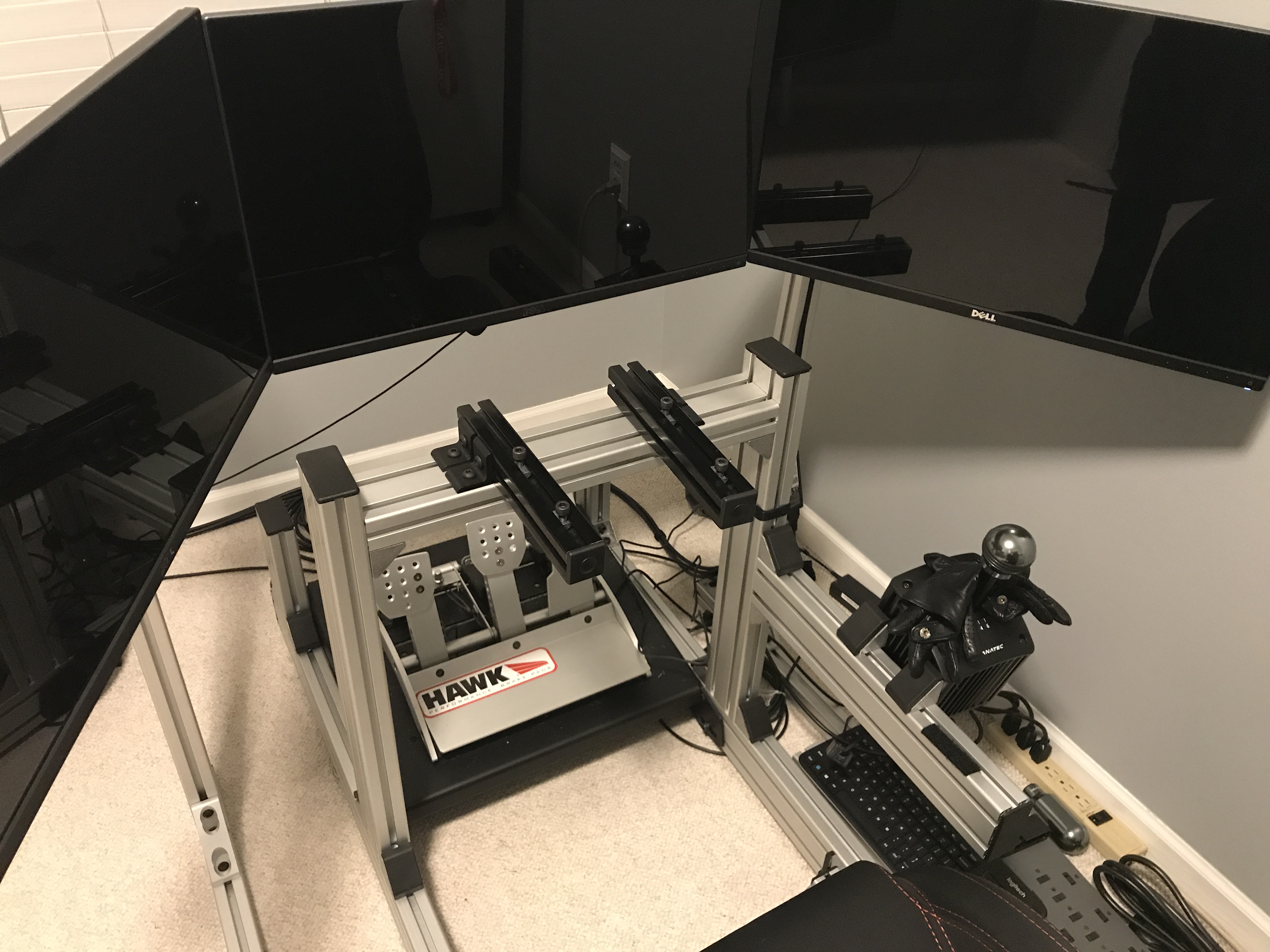
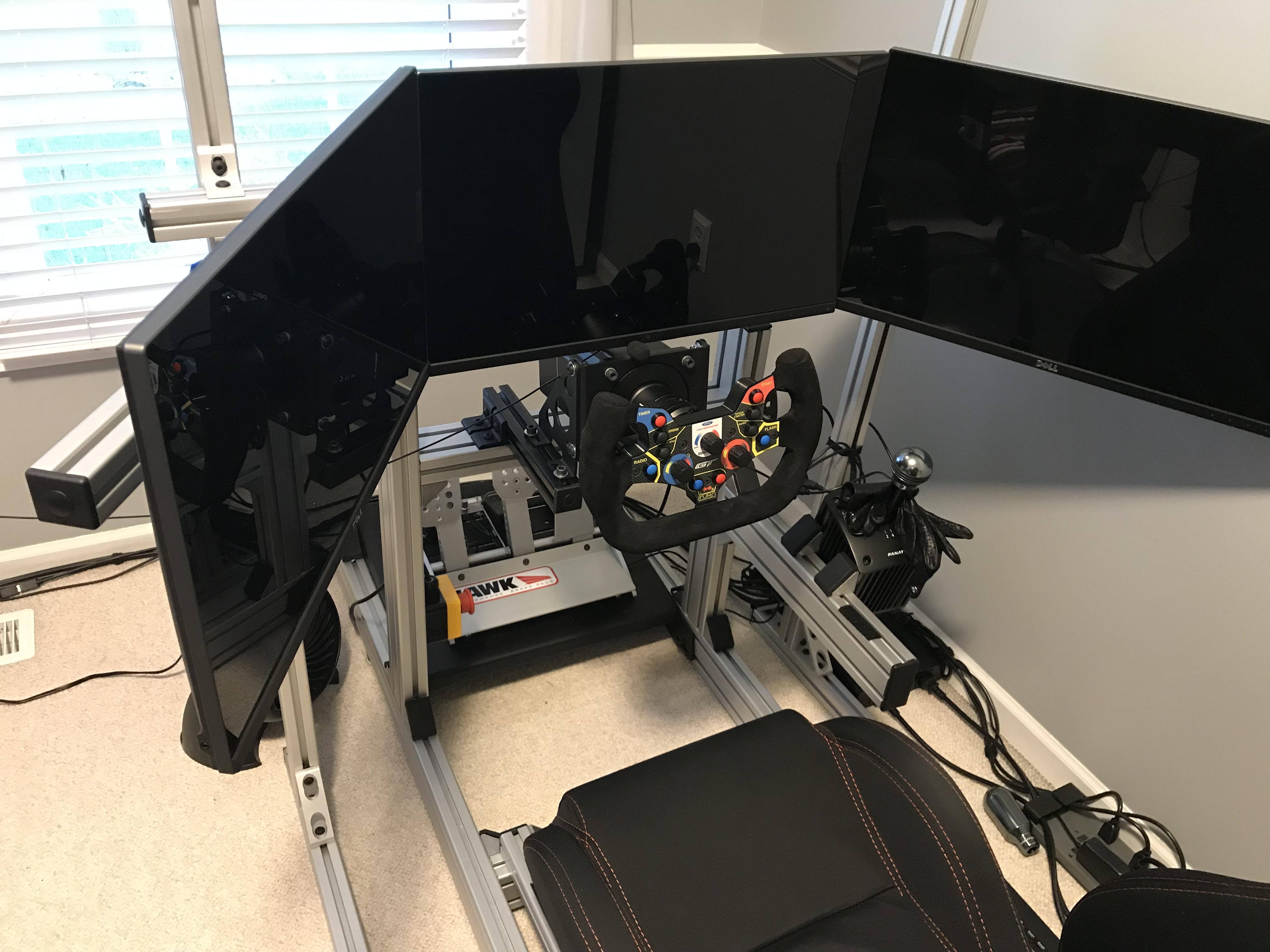
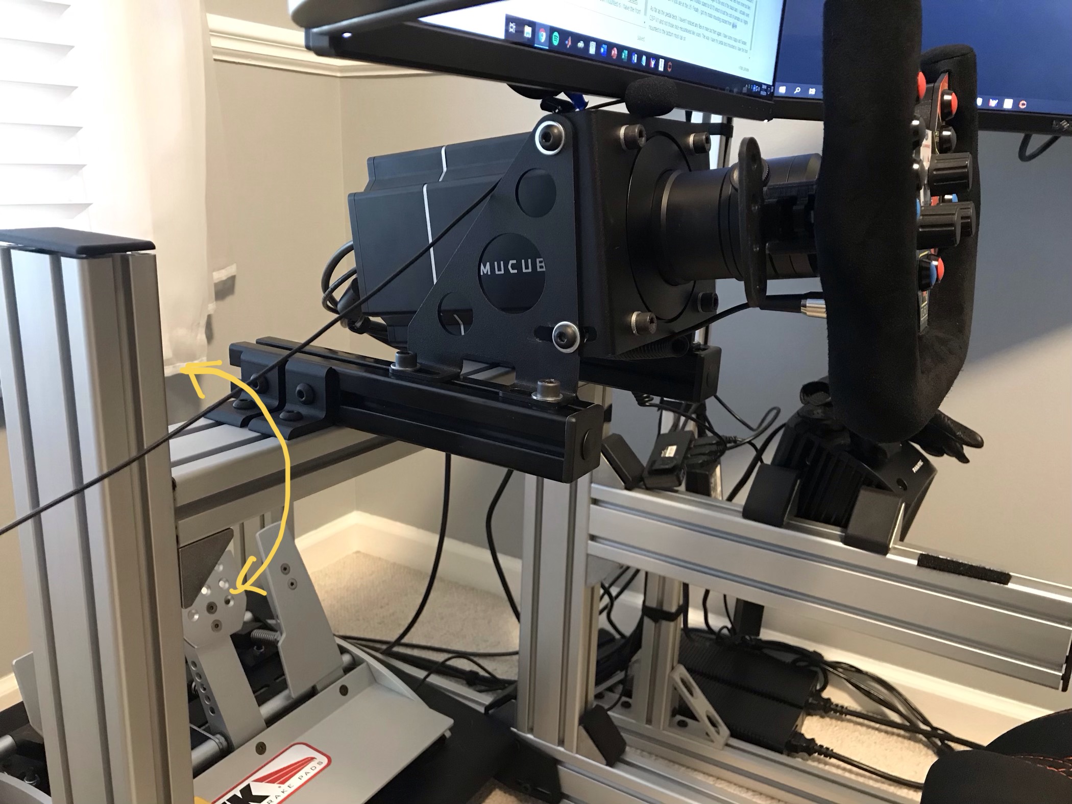
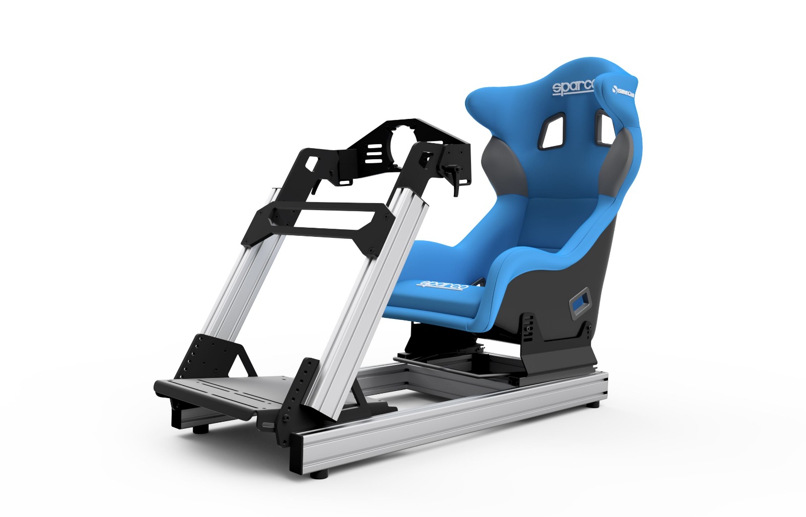
I also have a GT1 Evo and this how I mounted my SC2 Pro. It’s rock solid. All you need is two 40x40 aluminum extrusions and they will act as wheelbase rails. I can slide the SC2 forwards and backwards as well as tilt it using the bracket. If you want even more tilt angle, you can tilt the entire horizontal member that the two “wheelbase rails” are attached to. However, in order to do that, you’ll have to snap off the “anti rotation” tabs on the corner brackets joining the horizontal member to the two vertical members.
5 Likes
that is exactly what I was hoping to see thanks man!
just some questions :
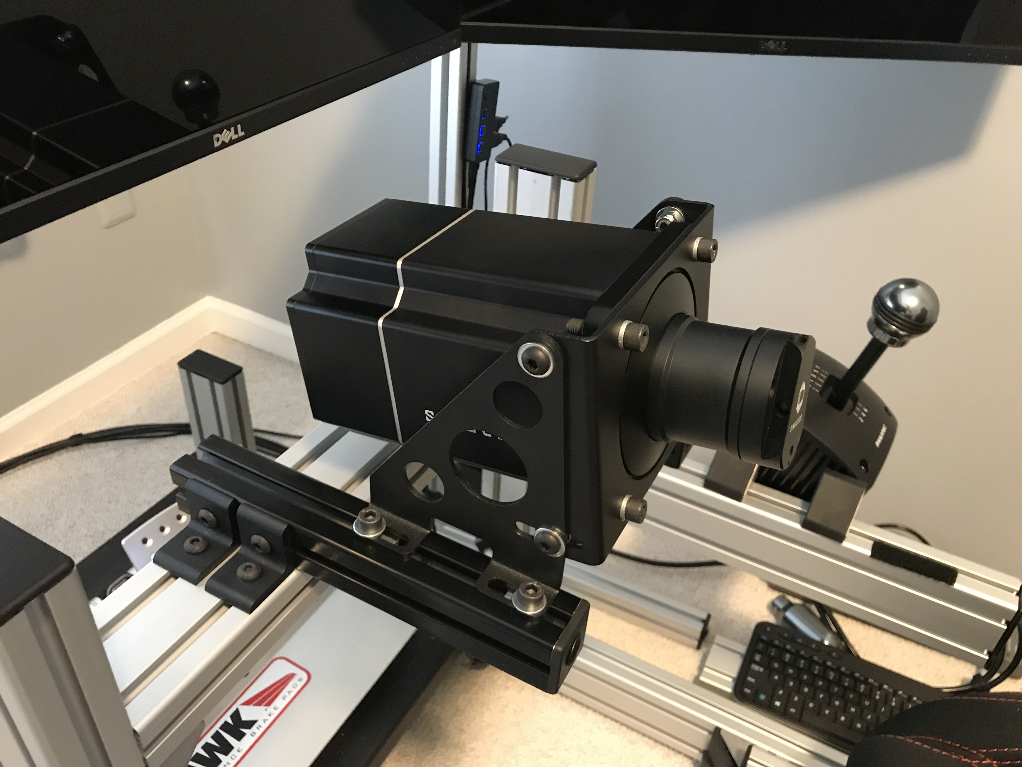
- being the motors mounted so far from the horizontal bar, doesn’t it have some leverage effect given the weight of the motor itself? do you feel those 40x40 bars are enough? I was thinking of 40x80 instead. also what’s the lenght of those black bars?
- where did you get those black bars and also the lateral mounting brackets? and the motor bracket ?
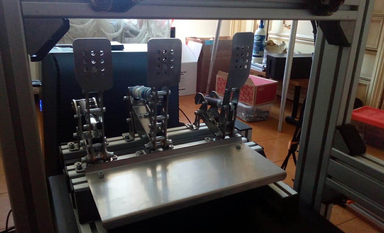
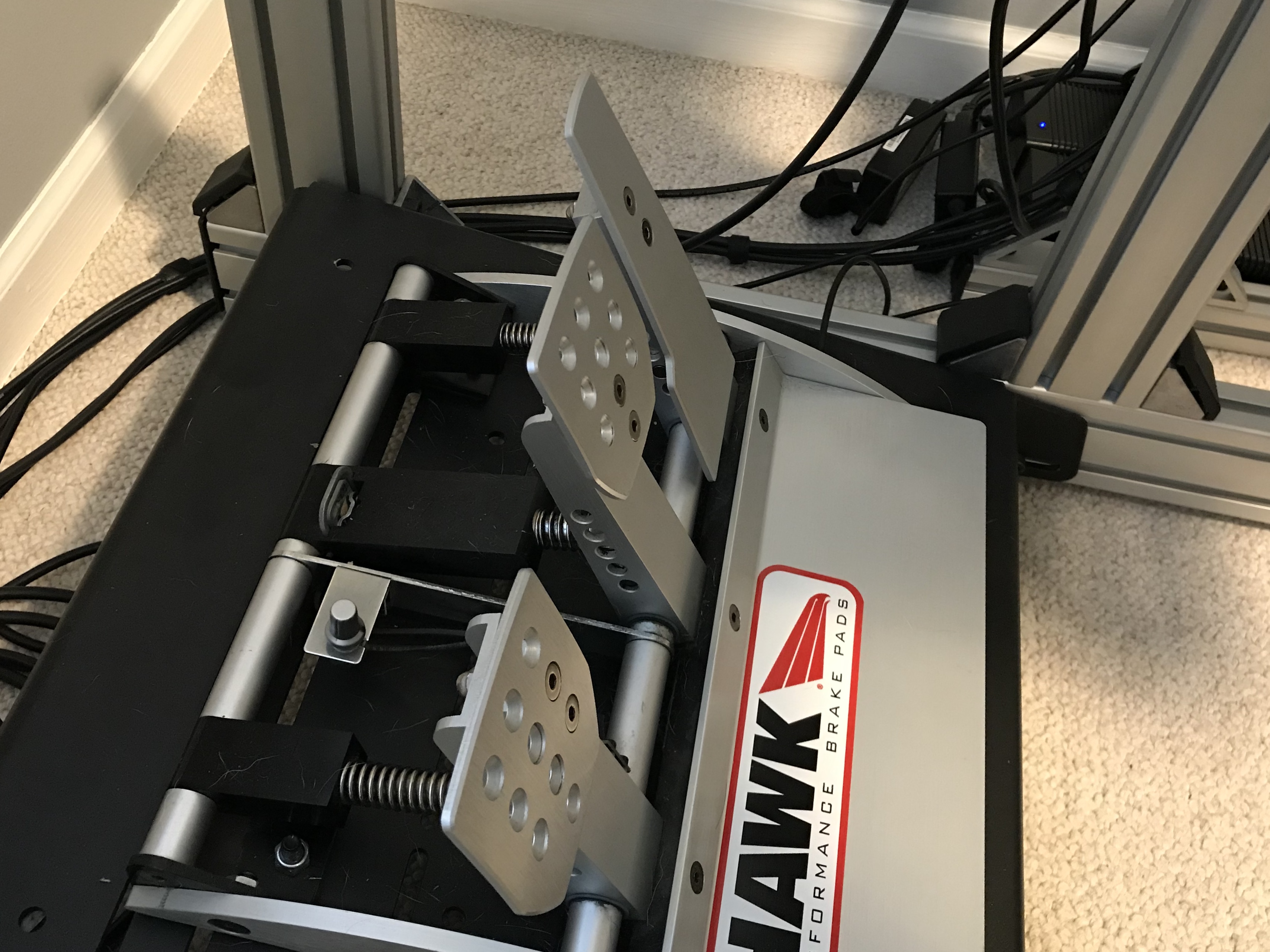
- not related to the wheel mount but to the pedals plate, I have the front part of the plate attached to the beginning of the vertical bar, not like you did on the base profile, do you think the way you did it may have some more rigidity? I am asking this becasue I needed to mod also the pedal plate with supplementar profile bars, because I was having some flex also on the pedal plate with my HE Pro pedals. This is what I did :
The black bars that I got are 10 inches long (254mm) and I can’t see/feel very much flex whatsoever even though the wheelbase is cantilevered all the way to the edge.
I got my aluminum extrusion and corner brackets from tnutz.com which is based in the US. The kind that I got is actually 15 series (1.5in x 1.5in which is almost identical to 40mmx40mm). The reason I did this is because it was cheaper than the stuff from 8020.net Using 40x80 will definitely help minimize flex even more but like I said, I can’t feel very much flex unless I apply my body weight to the end of the black bars. I actually used tnutz.com to design and build my triple monitor stand for $170 which is half the cost of simlabs so I highly recommend them if you are in the US. Finally, I got my motor mounting bracket from @Joe.
You can get more angle on the motor by actually tilting the horizontal member that I highlighted. You will have to remove the anti-rotation tabs on the corner brackets though.
As far as the pedal deck, I haven’t noticed any flex in mine but then again, I have some crappy old Fanatec CSP V1 and not those nice Heusinkvelds like yours. The way I have my pedal deck mounted is I have the front mounted to the bottom most slot on the bottom rail and the rear is mounted on the short vertical member to get a little bit of an angle. My next project is to build my own hydraulic pedals out of a wilwood floor mounted pedal set!
Let me know if need more pictures or info.
2 Likes
That’s all clear, thank you very much  I am gonna order the profiles from Motedis.com which is where basically every part of simlab rigs came from, so you have the same quality but for less the price. I live in Italy and they are based in Germany, so few days for shipment too.
For the pedals, I saw you keep them very low while I am used to have them a little higher, and because of that I mount the plate to the bottom of the vertical bar.
Those pictures were really useful, you gave me the exact idea I needed to solve my flex issue, so thanks again!
i will post the result in a couple of weeks, along with my new wheel I am waiting for
Yea my seat is quite low so that is why I have the pedals down low.
The other idea I am playing around with is inverting the motor mount. So now instead of the motor mounting on top of the black bars, it will hang down from them. So in other words, you’ll kind of have the motor positioned above but in between your legs so that you get a little bit more room for your knees. I’ll post pictures if I end up doing it.
2 Likes
bear with me with this highly detailed sketch I just made with the most advanced tool known to man aka Paint 3d :
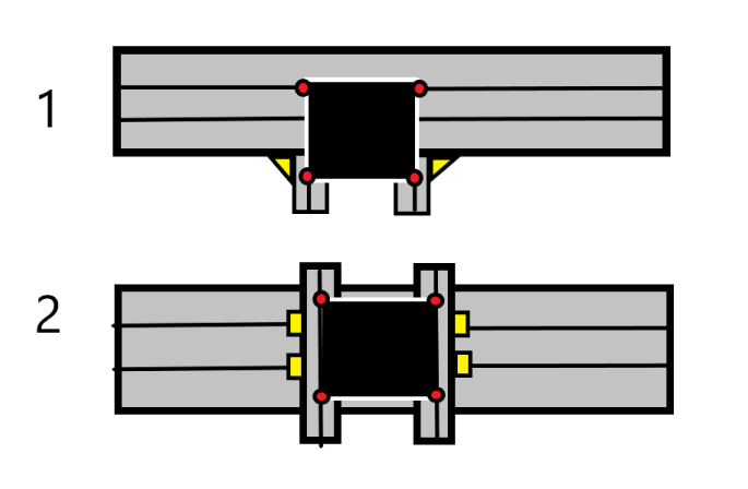
which is better for you and has the most rigidity ?
1 - the back of motor bracket on top of the horizontal bar itself and the front mounted on two 100mm bars t - mounted on the side of the horizotal bar
2 - the type of mount you are using too, but since I am going with the Augury bracket which is just 136mm long, the two bars will be no more than 160mm long (also not sure if 40x40 or 40x80)
Both cases, black square is the motor, the red dots represents the bracket mount holes and the yellow triangles / squares where the profiles are mounted on the horizontal bar.
2 Likes
Option 1 will definitely be more rigid since a short 100mm extrusion will have very little flex to begin with. Although if you want to be extra sure that it will be as rigid as possible, I would put corner brackets on both sides of the 100mm members. So a total of 4 corner brackets with one bracket on both sides of the 100mm extrusions. Just make sure that 100 mm is long enough to accommodate the mounting bracket mounting holes. If you want super overkill, you can use one of these on the bottom of the 100mm extrusions in addition to the corner brackets. That way you will secure the 100mm extrusions on three sides.
I considered doing your option 1 at one point but I decided not to do it because then the two main vertical members would be really close to my seat and it would make getting in and out of the rig a bit difficult. But if you have enough clearance for your seat and legs to be able to climb in and out of it, then definitely go for it! Or if you use a long extension between your wheel and the SC2 that would also work.
2 Likes
Not sure if you ever drilled large holes with hand drill, man, but this is text book.
Start with a Small Hole
Need a big hole? Start small! Most twist bits are available in sizes up to 1 in. in diameter, but you’ll get the best results by starting with a 1/4-in. hole and drilling successively larger holes with your drill bit for metal until you reach the size you want.
Why in the world would he need to drill a 1 inch diameter hole for this lol? The screws for the Auguri mount are 8mm (In case this doesn’t explain itself, 8mm is only 5/16th inch, which is only 1/16th larger than 1/4th, which is where that link tells you to start). I’ve never bothered drilling a hole larger than 1/2 inch by hand, but sure, if you have no other way to do large holes, then it would make sense to start with a drill bit smaller than the final hole diameter. But realistically, it would probably be easier to take it to a shop that has a drill press, or a mill, or a lathe.
If you’re talking about anything practical for the application we’re talking about, then no, you’ll just end up wearing out the drill bit needlessly if you’re only using the edge of the cutting faces, either that, or it’ll dig into the material and either mangle the plate itself, or chip the drill bit and make it useless.
1 Like
no more need to drill anything guys, I am gonna mount the motor as shown in the sketch above. no plates, no nothing. thanks anyway.
1 Like
Lol sorry for derailing the thread a bit.
1 Like
I could be, but I live in Italy…
I’ve got brand new, never used mounting from sim-lab. Drop me PM if any interest, I am in US.
1 Like
I have the TR1 cockpit which this new bracket is suppose to support so I have no option but to wait…But I’ll keep the offer in mind.
Regards