The one on your bottom picture is the current revision of the Simucube 1 board, where there is a jumper selector soldered for easy switching to an external braking resistor if desired. The jumper is in place there, and in the position as pictured, it is selected to use the internal resistors on board the PCB.
But, it does not remove the fact that the connector block is indeed missing.
While I do answer for the software related support, our hardware engineers have been hard at work onboarding a new dedicated support person this week, and we apologize that your support ticket has been unanswered.
Mika,
Thanks!
Already got a response and the problem will be solved.
Regards
Ok…just one quick question:
I had the connector soldered but the technician that soldered it asked me if it was missing a resistor/transistor where I circled in red. Is it?
Can someone confirm?
Thanks.
Regards
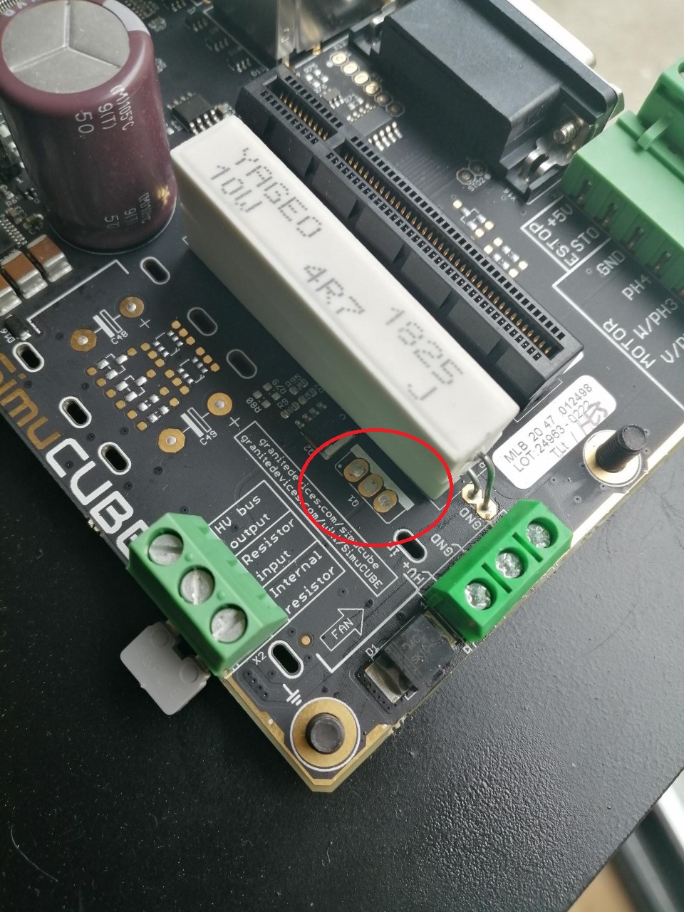
I think the surface mount transistor next to it (to the left) is the current design. The through-hole mounted part became obsolete and that was one of the reasons we had to revise the Simucube 1 board back in 2017 I think.
But I will need to confirm this. Unfortunately it is the Easter holiday here and we are back in office on Tuesday.
Thanks again, Mika.
The Simucube troubleshooting page
https://granitedevices.com/wiki/SimuCUBE_troubleshooting
has a picture of the latest build. It seems I’m good to go 
Regards! Happy Easter!
Mika is spot-on as usual, that through-hole component was replaced by the SMD next to it. I have fixed a few in the older days when the Regen circuit failed due to incorrect FOV settings people might set with certain servos.
Then I replaced the SMD’s with through-hole devices, as it was easier to solder. But anyway, your board should be good to go now, have fun
Great!
Thank you both!
Regards