Hi community!
I have been reading these pages since I built my own Simucube 1, almost 2 years ago. It has been a very informative and helpful source of ideas and solutions.
Now I decided to upgrade my button box, and would like to use the full potential that Simucube has to offer but I am stuck.
I am trying to work out a solution for using the shift function WITHOUT having a physical shift button.at all.
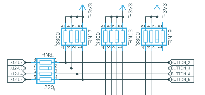
Unless I made a mistake in the attached drawing, I should be fine with the port X12 UPPER and my first 12 buttons.
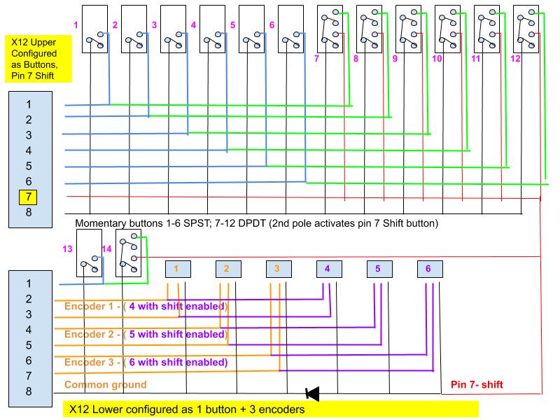
I am a little unsure about how I configured X12 LOWER in the drawing:
I want to effectively have 6 encoders rather than 3 that serve a second function when shift is pressed.
The problem I see here (I am not an expert in electronics) is that if I join pin 8 ground with X12UPPER pin 7, encoders 1.2 and 3 will clone 4.5 and 6.
In order to avoid that I put a diode between 1.2.3 and 4.5.6 ground pins. However i am not sure whether this will work.
Should this work, what value should the diode be? Could it be an LED instead, so that I can place it on the button box and see when my shift function is enabled.
Any thoughts will be highly aprreciated
Thank you for taking the time to read this
Cheers
Claudio