Show the motor current values or paste the bottom part of the Testing tab here.“copy device state to clipboard”
[ ] Initialized !
[ ] Error recovering
[ ] Tracking error warn
[ ] Target reached
[ ] Enabled !
[ ] Run (drive active)
[ ] Homing active
[X] Braking
[X] Permanent stop !
[X] Voltages good
[ ] Fault stopped
[ ] Ready for use
[ ] STO active
[ ] Tracking error
[ ] Over velocity
[ ] Hardware
[ ] Over temperature
[ ] Feedback
[ ] Over current
[ ] Internal comm error
[ ] Power stage forced off
[ ] Under voltage
[ ] Over voltage
[ ] Motion range
[ ] Firmware error
[ ] Init
[ ] Motion
[ ] SimpleMotion
Fault location ID1 0 (info)
Fault location ID2 0 (info)
! = reasons for inactivity[X] GPI 1
[X] GPI 2
[X] GPI 3
[ ] GPI 4
[ ] GPI 5
[ ] GPI 6
[ ] HSIN 1
[ ] HSIN 2
[ ] ANA1 as digital
[ ] ANA2 as digital
[X] ENC A
[ ] ENC B
[ ] ENC C
[ ] ENC D
[X] Hall U
[ ] Hall V
[ ] Hall W
[X] Soft enable
[ ] Phys enable !
[ ] Pos feed enable
[ ] Neg feed enable
[X] Home switch
[ ] Clear faults
Analog in 1 0.01 V
Analog in 2 0.00 V
Analog Enc A 3.66 V
Analog Enc B -3.61 V
HV bus voltage 47.8 VDC
Device temperature 31 °C
Actual current limit ±2.0 A
Last limit reason None
Output current 0.38 A
Velocity feedback 0 r/s
Velocity feedback (raw) 0
Position feedback 0.0028 r
Position feedback (raw) 28
Setpoint value (raw) 0
Debug 1 -1
Debug 2 -1
Debug 3 -1
Debug 4 -1
Debug 5 -1
Debug 6 -1
Parameters
| GCFWVER=10709 | HWTYPE=11201 | HWSERIAL=112011536 | BUILDREVISION=26dccc43
| CEI=0 | UID=23ba7086 | SMO=0 | TRF1=0
| TRF2=0 | TRA1=0 | TRA2=0 | MPP=0
| NOTCHFILT=5.24336e+06 | TED=0.6 | TEF=0.5 | TEI=0
| SERIALENCBITS=6 | COMMUTATIONCFG=0 | HAO=0 | FBR=2500
| FBD=1 | FB2D=0 | TBW=1 | KVP=300
| KVI=30 | KPP=50 | VFF=0 | AFF=0
| PFF=85 | CM=2 | MT=0 | AD=0
| FLAGS=131072 | MMC=2 | MCC=1 | FOC=2
| FOV=52 | FUV=20 | FPT=1000 | FVT=100
| FEV=100 | FMO=0 | LSF=0 | AXS=1
| AXT=3 | FFT=0.1 | TSR=15 | TCH=126
| TTR=1 | TBT=0 | CRI=0 | DIV=50
| PIF=2500 | MUL=50 | CAL=10 | CSD=10
| CVL=1000 | CRV=100 | MR=0.4 | ML=0.8
| MTC=500 | MPC=8 | MMS=3000 | CAO=0
| HOMING=0 | HMV=100 | HMA=10 | HMH=0
| HMT=1 | HHL=0 | HLL=0 | HMF=0
| HSA=0 | HSS=0 | overrideAddr1=0 | overrideAddr2=0
| overrideAddr3=0 | overrideVal1=0 | overrideVal2=0 | overrideVal3=0
| BED=1.5 | BER=0 | BDD=1 | CAPS1=6.29143e+07
| CAPS2=81823
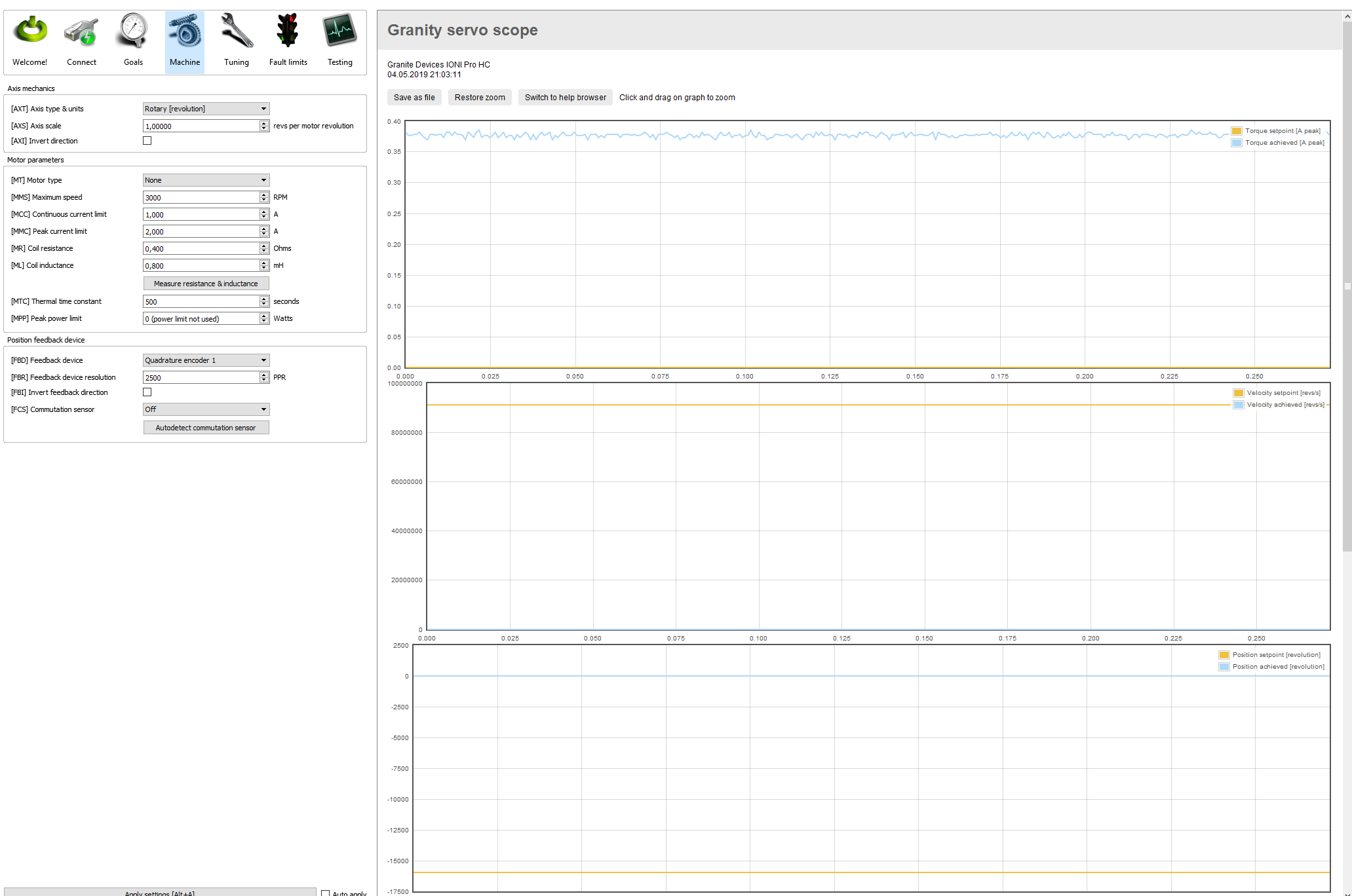

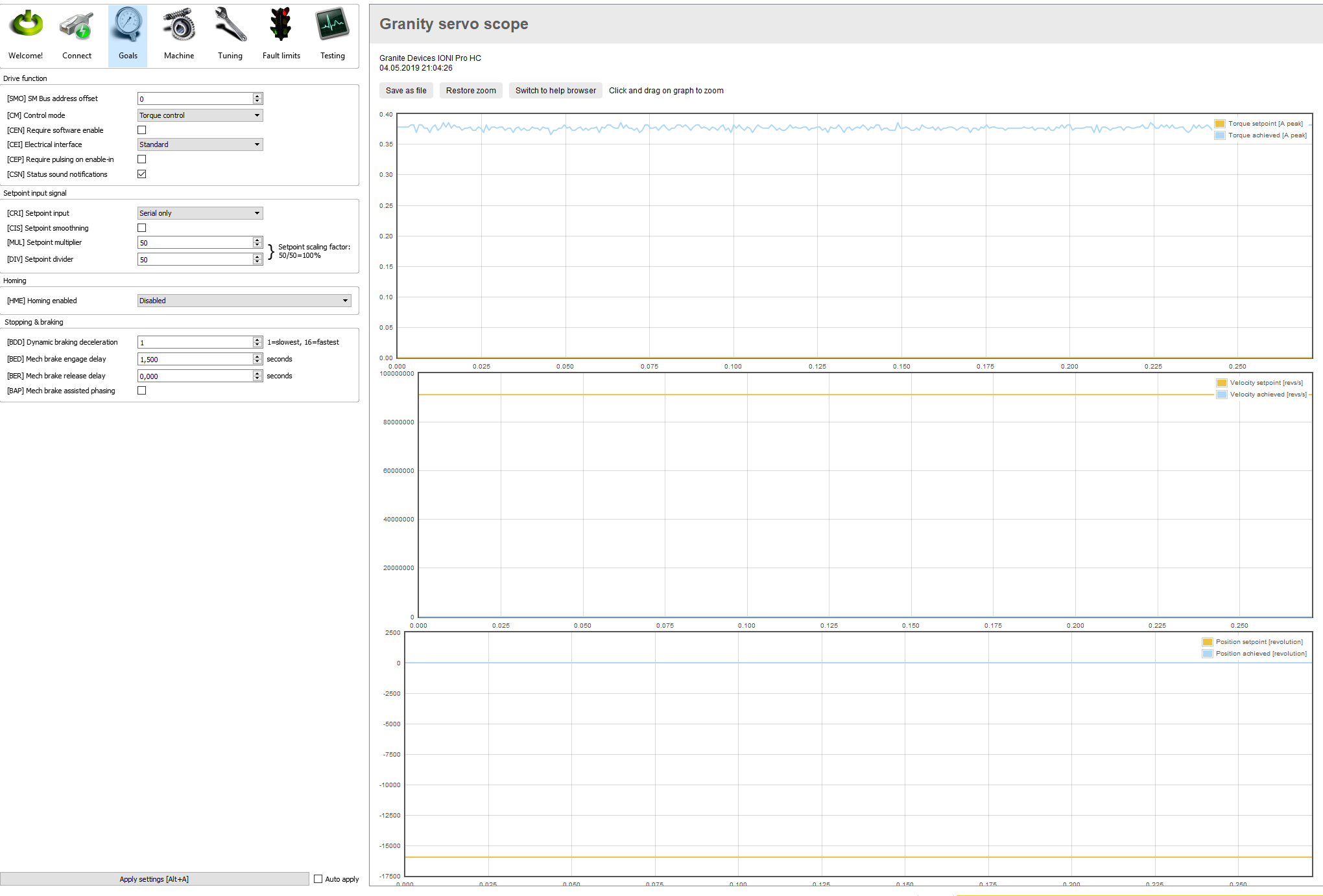
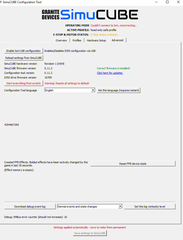
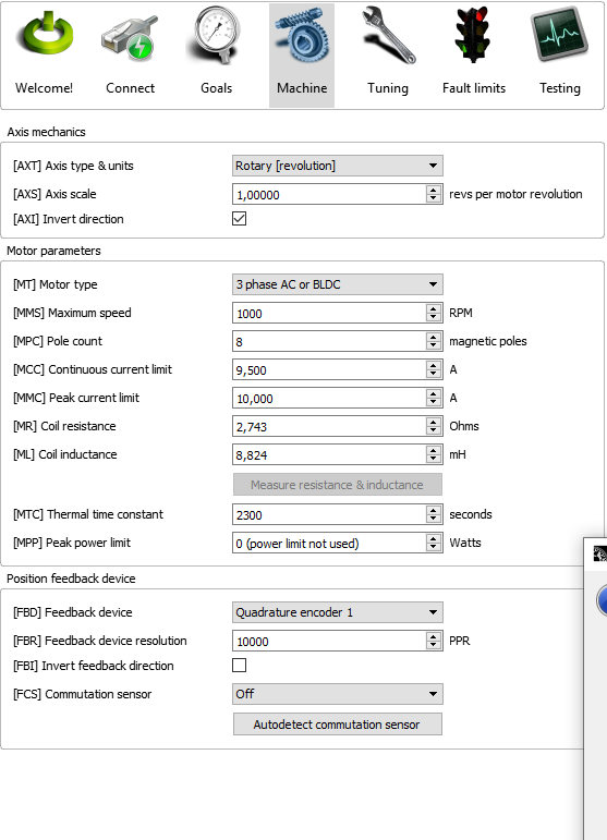
Your settings seem to be at default settings, so it won’t work in Simucube. Which motor and encoder do you have? If you don’t know, see the receipts for your kit etc.
Open sim wheel SimuCUBE MiGE 130ST-M10010 20Nm 10000ppr
Save this DRC file and load it with Simucube Configuration Tool or with Granity.
10010_MAX_480w-48v_10Kppr.drc (9.2 KB)
Should be, if it works. 
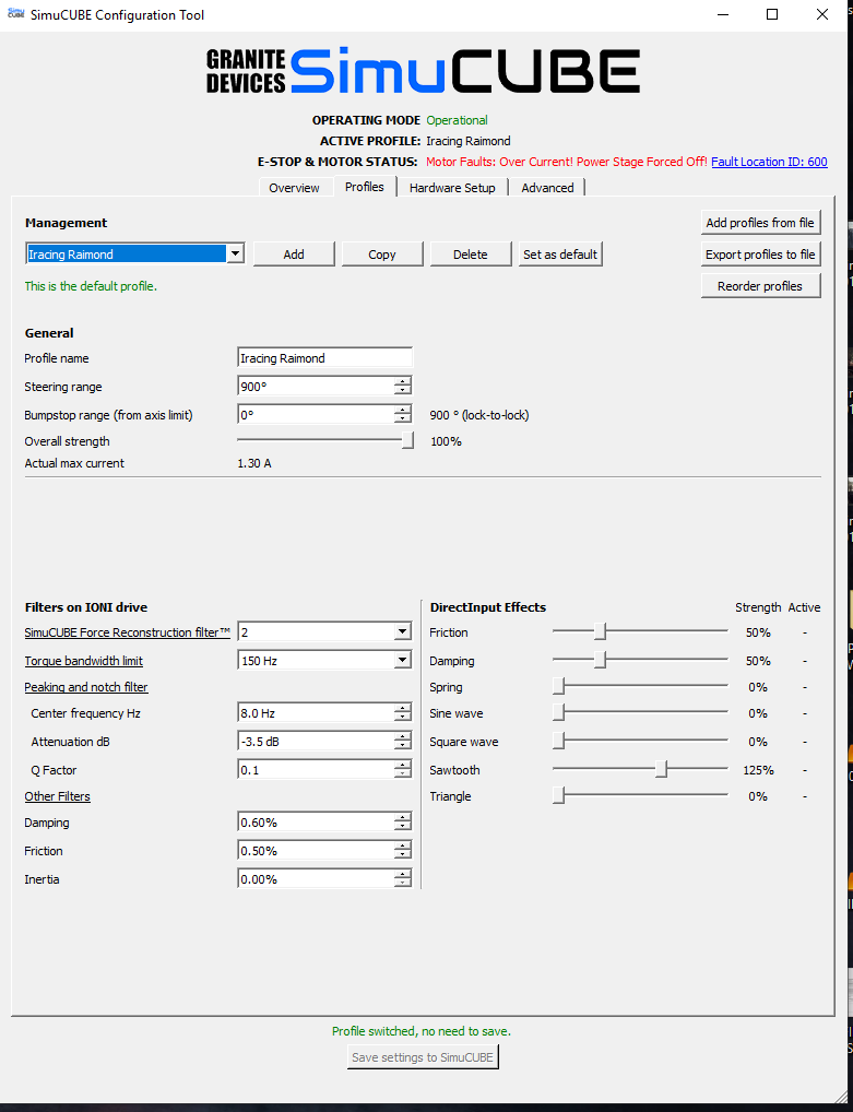
Remember to set the bumbstop settings at least once to nondefault values, then you will also have Force feedback.
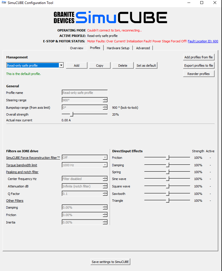
Now what happens is that when you turn it on it is an operational time but soon after the wheel turns sharply with a whistle and the wheel is more rigid, as with energy, and says this;
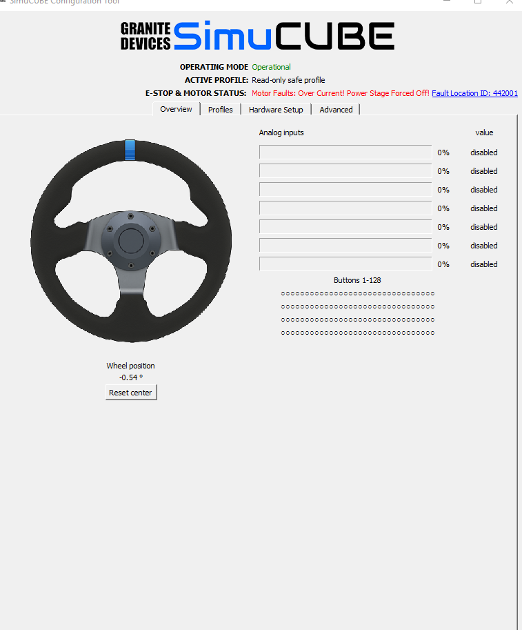
Now what happens is that when you turn it on it is an operational time but soon after the wheel turns sharply with a whistle and the wheel is more rigid, as with energy, and says this
It seems that the wheel has gone crazy!

Try this drc : -------
It seems to work, tomorrow I will continue testing
Thanks to you and mika, good job
Do you know what psu your system has?

Ok , connect with granity and in the motor tab press the button to meassure the resistance and inductance , when it changes the values of mr and ml press ok and then save and try the system again.
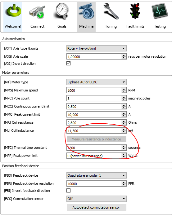
Apply the new values, save and disconnect
Show us all the settings again.
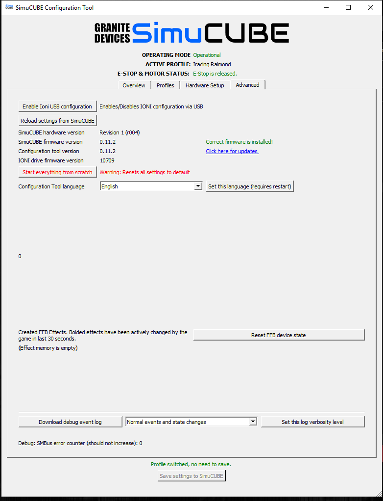
Did you manually update IONI firmware and reset its settings when you had default settings yesterday?